How to print large objects using LCD
without warpage and shrinkage
Printing large objects, particularly ones with large flat surfaces is challenging in large format LCD printers. If you follow the guidance given below you can print any object, given the correct printer, resin, software, print expertise and some design freedom.
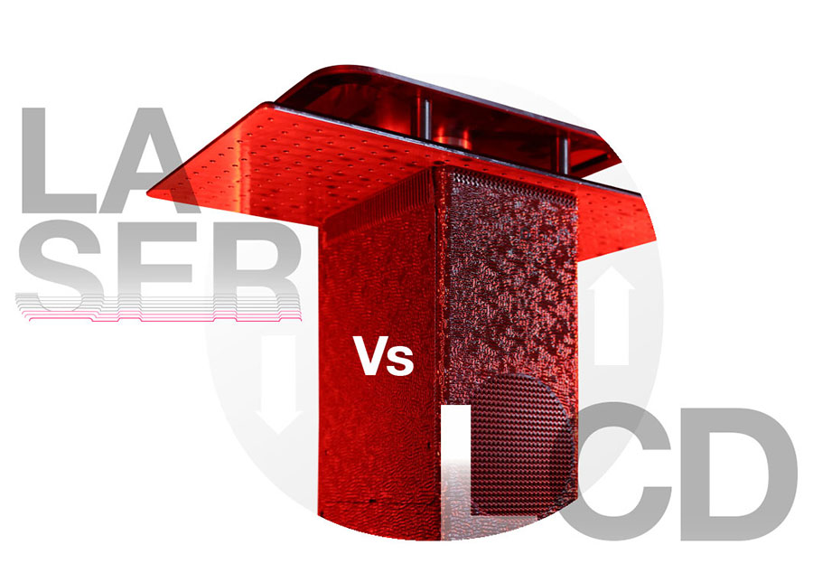
Comparison to conventional technology
Large format SLA systems use lasers to polymerise resin cationically, top-down into the vat. Cationic curing, by virtue of cations ring opening, inherently has lower shrinkage than the free radical cured process used in LCD screens where double bonds reconfigure in single ones to polymerise the resin. Furthermore, as conventional systems are top-down, the viscous fluid supports the printed object as it descends into the vat. Both attributes make printing dimensionally accurate objects in this manner simpler to do. However, if you follow this advice, you can make accurate large objects free radically cured, bottom-up, in LCD printers, achieving the same results, and in doing so, reap the benefits of a wider range of physical properties and create durable, functional parts at a fraction of the cost and time, in considerably larger quantities.
The benefits of LCD
The benefits of creating objects using free radical chemistry and the practicality of printing bottom-up are significant. LCD printers expose the polymer simultaneously, as opposed to voxel by voxel; this increases the capacity to create solid objects by an order of magnitude over a laser beam. LCD is also consistent, even across a very large build platform; unlike lasers, the curing area of which becomes more ovaloid the further it moves towards the edges of the build platform. LCD benefits from being the most reliable mechanism of creating an image, lasers require maintenance and focusing. LCDs also use considerably less energy than lasers. The free radical chemistry utilised in LCD printers, in comparison to the 355nm resin used in large format printers, delivers the widest variety of usable properties from extreme flexibility through toughness, durability, to hardness, it also polymerises much faster. These free radical resins are not only cheaper, but if well-constructed, will last forever, delivering phenomenal user properties at much lower prices.
All these factors, combined with their lower capital cost and lower running costs, make LCD the only option to transit 3D printing out of prototyping into mass manufacture. Large vats of resin represent a huge cost, 800kg of resin in a top-down printer could cost €300k, (in contrast just 7kg in a large format bottom-up LCD printer costs around €300) and they are a huge liability as they have a risk of polymerisation over time. Furthermore, the parts are immersed in liquid, so carry resin with them, the transfer process either requires draining the vat or lifting it up, which is problematic in large systems. For these reasons the best way of scaling up large part production, is to print bottom up.
Tips
These are the tips and techniques necessary to print a large object using free radical chemistry bottom-up and make it dimensionally accurate.
How to design with free radical in mind
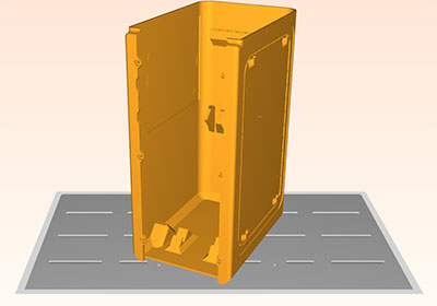
This chassis was designed by Photocentric’s engineering team who wanted to make a new printer housing for their autonomous printing process.
If it was just placed flat on the build platform like this it would shrink in on itself, naturally releasing the inbuilt tension by leaving all the faces curving in. None of them would be true or at 90 degrees to each other.
Using the design changes shown below you can reduce peel force and eliminate the negative effects of shrinkage.
Support where necessary
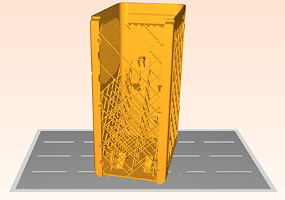
We have internally supported the chassis using VoxelDance to push out in all places where it wants to push in. The objective here is to fix the shape of all the sides in the same position we want them to be in at the end of the print. We have cross-braced the structure, so the supports run at 45° to the faces and all the forces are constrained, retaining it in the desired shape.
To make this process easy, use an auto support software function, such as Autodesk, Photocentric Studio or VoxelDance.
Supports must have small enough tips to make removal easy but be strong enough to withstand the shrinking forces.
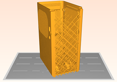
Replace holes with press-outs
It is imperative to design all panels, so they have constant force on them, externally and internally.
When the printing process arrives at a hole or cut out in the layer the forces will change. You must negate those by replacing them with cutouts. If you design in twist off tabs these can easily be removed after printing.
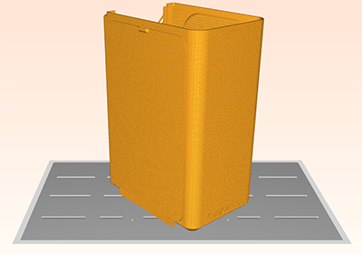
Lattice suitable surfaces
Lattice any non-facing panels to reduce weight.
All four of these panels in the chassis can now be printed and will be true to their intended design specification after post-exposure.
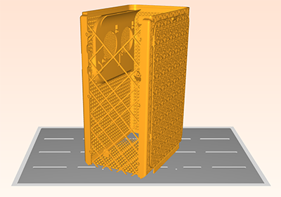
Texture the outside faces
Here we have taken a lattice from the Photocentric Additive database, to apply a deep diamond texture on the outside faces.
This further reduces surface forces while printing, dissipating them across each layer evenly.
It will have the added benefit of covering the print layer lines and making the part look like an injection moulded part.
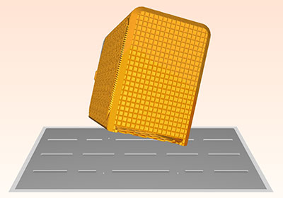
Orientate the part correctly
Here we have positioned it so that the print platform is at an angle, to every one of the faces. This deflects any forces during platform lift so they don’t have any more significant effect on any one side. This evenly distributes the forces and prevents distortion.
We have ‘chocolate-blocked’ the base of the chassis to improve its rigidity and strength and make it easier to clean and remove from the platform. We supported it automatically in this orientation.
Process the part correctly
The chassis was printed in Daylight Magna Hard Black resin at 250μm layer thickness on Liquid Crystal Magna. The print took 15 hours to complete, taking 900ml of resin including supports. The part was processed on the platform to neutralise any shrinkage forces during post exposure. It was washed for 15 minutes in Photocentric Resin Cleaner, rinsed with warm water, and then air dried before being post cured in a Photocentric Cure L for 2 hours. Excessive use of the wrong solvent can swell and distort the part. Once finished, the parts were removed hot from the cure unit and submerged immediately in cold water to thermal shock them off, allowing the part to be effortlessly removed from the platform and not subjecting it to damaging forces.
250μm layer thickness
Print time 15 hours
900ml of resin used
Parts washed and cured in 2 hrs 30 mins
Parts thermal shocked
And finally, and most importantly…. print in daylight not UV
Less is more, often in life and in energy when curing polymers. Daylight cures with a more consistent cure-through-depth profile compared to UV, which makes visible light exposure more forgiving than UV. Daylight ensures cure depth is level across the entire build area, and is less sensitive to variations in exposure intensity, wavelength or temperature. This leaves parts fully polymerised without internal distortion built-in when composed of numerous high energy bonds surrounded by non-polymerised material.
In UV (405nm) LCD printers >95% of the light is blocked by the panel and converted into heat. Photocentric specify the highest quality, energy-efficient blue daylight LEDs which enable maximum light delivered with minimum heat.
Unique features only enabled by 3D printing
Several features of the chassis design were made possible by 3D printing the chassis as opposed to manufacturing with conventional methods:
Print-in-place magnetic door panel- this panel allows access to the internal components for assembly and maintenance and can be printed in-situ without needing a second print file. It also acts as support material for the aperture it covers, which stops warpage and greatly reduces material wastage in unnecessary support material.
Fully integrated part fitting- using magnets and captive nuts inserted after print, but before post exposure, as opposed to tapping holes after printing, thus making it easier to optimise for mass production.
Reduction in extra components- many features can be directly integrated into the printed design, for example, cable ties can be replaced with printed retention clips, the fan filter and plenum were directly integrated into the panel side, and a diffuser panel was added for indicator LEDs.
Customisation- different surface textures were applied and a company logo was added to the front of the chassis.
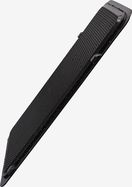
Lattice liner applied to the side panel removing warpage
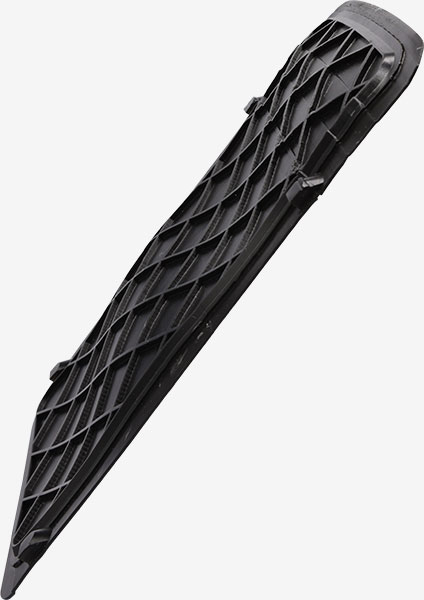
Panel without lattice layer warped