Liquid Crystal Magna Resource Hub
Contents
Getting started with Magna
What you receive
Magna
You will receive a Magna 3D Printer that is ready to start printing with, and its accessories box.

- Print platform knob- used to secure and release the print platform from the arm.
- Print platform- an aluminium assembly with the following features:
- ResinGlide coating for easy cleaning, removing excess resin.
- Roughened print platform surface to increase print adhesion.
- Pre-calibrated in the factory to ensure that the bottom surface of the print platform is planar parallel with the LCD screen.
- Interchangeable print platforms that can be swapped between printers without the need for re-calibration or homing. It is recommended that 2 or more platforms are dedicated to one printer.
- Resin vat- Contains the resin required to complete print jobs, featuring:
- Spouts to pour resin back into its container.
- Volume gauge to indicate the amount of resin inside the vat.
- Durable vat film delivering low adhesion at peel and accurate prints over a long life.
- Shut off/Reset button- if a resin leak occurs it can enter the vat leak sensors, the sensors prevent resin from damaging the ‘Blow-Peel’ system by shutting off the valves and alerting the user with an alarm. There is an explanation of the cleaning procedure after a vat leak in the maintenance section.
- Power button- turns the Magna on and off, can be used to cut the power in case of an emergency.
- USB port- transfers sliced files via the USB Flash Drive provided or, any non-password protected USB.
- Touch screen GUI- interactive GUI allows users to control, connect and maintain Magna.
- LCD screen- 24” 4k LCD screen displays the slices of the print file, curing the layer of resin between the vat film and the print platform. The screen is covered by a clear screen protector.
- Door switch & interlock- safety feature to abort print arm movement if the door is opened during printing.

- Lifting handles- when moving Magna to a new location these lifting handles can be used. Please refer to the Installation Guide for further guidance.
- Extraction port- to connect Magna to an external extraction unit if required. Please refer to the Magna Installation Guide for further guidance.
- Power connection- this socket has been carefully selected to ensure a secure and reliable power inlet.
- USB port for Wi-Fi dongle- to plug in the provided Wi-Fi Dongle to enhance Magna’s Wi-Fi detection and connection to a secure local wireless network.
- RJ45/Ethernet network connection- Magna can be securely connected to a LAN or RJ45 network.
Accessories Box

| 1) 1 x power cord | 7) 1 x Pozi2 screwdriver | 13) 12 x foam tip swab | 19) 20 x small vat screws- to re-skin the vat film |
| 2) 1 x 32GB USB | 8) 5 x paper resin filters | 14) 4 x pipette | 20) 20 x large vat screws- to re-skin the vat film |
| 3) 1 x Wi-Fi dongle | 9) 1 x funnel | 15) 1 x blow peel gasket | 21) 2kg Hard black & 2kg Dental Model white resin |
| 4) 1 x extraction spigot 100mm | 10) 2 x pairs of gloves | 16) 2 x vat gaskets | |
| 5) 1 x scraper | 11) 1 x vat cleaning tool | 17) 2 x vat film | |
| 6) 1 x Pozi1 screwdriver | 12) 1 x soft spatula | 18) 1 x vat cleaning foam mat |
Accessories Box

1) 1 x power cord
2) 1 x 32GB USB
3) 1 x Wi-Fi dongle
4) 1 x extraction spigot 100mm
5) 1 x scraper
6) 1 x Pozi1 screwdriver
7) 1 x Pozi2 screwdriver
8) 5 x paper resin filters
9) 1 x funnel
10) 2 x pairs of gloves
11) 1 x vat cleaning tool
12) 1 x soft spatula
13) 12 x foam tip swab
14) 4 x pipette
15) 1 x blow peel gasket
16) 2 x vat gaskets
17) 2 x vat film
18) 1 x vat cleaning foam mat
19) 20 x small vat screws- to re-skin the vat film
20) 20 x large vat screws- to re-skin the vat film
21) 2kg Hard black & 2kg Dental Model white resin
Getting ready before receiving your printer
Ambient light
Operate your printer in a low-light environment. Always avoid direct sunlight. Red lighting is ideally used as it does not interact with the resin. It is advised to handle resin in a low light environment away from direct sunlight. Operating temperatures should be constant ideally between 20 and 25°C.
Space/location
Liquid Crystal Magna weighs 110kg. When choosing a suitable location for your Liquid Crystal Magna, make sure the space is appropriate for the weight and allow plenty of access area (see Figure 3 and Figure 4). All diagrams have dimensions in millimetres unless otherwise stated. Consider the ergonomics of operating the machine.

Extraction
Liquid Crystal Magna has an extraction port on the back, with a cover plate. The cover plate is attached by four screws (Figure 9). A 100mm spigot is supplied in the accessory box. This can be attached to the back of the machine if the cover plate is removed. Re-use the four screws to secure the spigot. This will allow you to connect 4-inch ducting to the printer.
Extraction is recommended if Magna is operated in a confined or poorly ventilated space. It should not be necessary in most cases. The fumes from the printing process are not harmful, but the odour can be unpleasant. The volume of air inside the printer is approximately 320 litres (0.32 m3). A maximum of 2 air changes per minute should be used. This corresponds to a flow rate of 640 litres per minute or 38 m3 per hour. Using a higher flow rate will cause excessive cooling of the resin which may affect print performance. It will also increase the noise level and may draw dust into the printer. In cases where a higher extraction flow rate must be used, most of the fumes can be removed from Magna in just a few minutes. After each print is finished, turn on the extraction for a short period before opening the printer door.
Photocentric recommends BOFA extraction systems to connect to the Liquid Crystal Magna printer and the Air Wash L station. For more information click here.
Power
Liquid Crystal Magna requires an earthed mains power supply with a voltage of 100 VAC – 240 VAC and a frequency of 50 Hz – 60 Hz. It has a peak power consumption of 1300W and an average power consumption of 500W. It will draw a current of 7.0 A when connected to a 240 VAC supply, or 13.5 A when connected to a 100 VAC supply. Only connect Liquid Crystal Magna to the mains socket using the power cable supplied. The printer power socket is on the back of the machine, at the right side (Figure 10). Always plug the power cable into the mains socket and the printer before switching on the power at the mains socket. Similarly, always switch off the power at the mains socket before unplugging the power cable from either the printer or the mains socket. The power button is on the front of the machine, at the right side (Figure 11). In case of emergency, switch off the printer by pressing the power button.

Connectivity
- Liquid Crystal Magna has a USB socket and an RJ45 network socket on the back.
- Plug a Wi-Fi dongle (provided) into the USB port if you would like to access your printer via a Wi-Fi network connection.
- Plug a network cable (eg CAT6) into the RJ45 socket if you would like to access your printer via a wired network connection.
- The USB socket on the front of the printer allows you to upload print files via a USB flash drive.

Minimum system requirements
- Windows 7, 8 or 10.
- Minimum 2.0 GHz processor speed 2 Cores recommended 4 cores.
- GPU capable of running OpenGL version 3.0 or higher. We recommend that you use GPU with at least NVIDIA GTX1050 specifications.
- .net framework version 4.0
- 64bit system: minimum 2Gb of Ram, recommended 4Gb.
- 32bit system: minimum 1Gb or Ram, recommended 2Gb.
You can run the software using MacOS by using a virtual workstation with Windows installed on it.
Installing Magna
Un-crating Magna
Store the crate for future use.


Lifting LC Magna
We recommend using a forklift truck or pallet truck to handle your Liquid Crystal Magna. Lift the printer from the front or back, not the side. Adjust the fork spacing so that both forks fit between the feet. Make sure that the forks reach fully under the printer before lifting, this way the weight is distributed across structural parts of the printer chassis.


Lifting Magna incorrectly could cause serious damage to the machine. If the printer is being carried any distance by forklift truck, secure it to the forks using ratchet straps to prevent it moving or bouncing on the forks. Pieces of rubber mat can be used to protect the printer from being damaged by the forks.
Alternatively, you can lift Liquid Crystal Magna with a winch or hoist. Make sure the equipment used is rated to carry the load. Remove the door of the printer by unclipping the hinges (Figure 7). Always support the weight of the door. This is a two-person task. Remove the two rectangular panels on the back of the machine (Figure 8). Two lifting straps can be threaded through the machine from front to back. Secure both ends of each strap to the lifting hook. Make sure the straps are rated to safely carry the load. Be aware that the straps may move as the machine is lifted. Pieces of foam or cardboard can be used to protect the printer from being damaged by the straps. If the printer is being carried on a mobile hoist, always keep it steady and under control.
If it is necessary to lift Liquid Crystal Magna manually, four people will be required. Remove the door and cover panels as described above. This provides four secure handholds at the top corners of the printer. It is also possible to lift the machine at the base. It may be safest to lift the machine in two stages. Use a low table or a stack of pallets to provide a stable surface at an intermediate height. Use safety gloves with a secure grip surface to prevent slipping. Ensure everybody involved is comfortable with the weight. Follow proper safe lifting practice. When lifting the printer at the base, always keep it level and stable.


Printer set-up
Your printer will now be in a suitable place, ready to be set up. The power socket is on the back of the machine on the right-hand side. Only connect Magna to the mains using the power cable provided. Always plug the power cable into the mains socket first, then into the printer before switching it on, using the power button at the front (as shown below). Similarly, always switch off the power at the front before unplugging the power cable.
Once Magna has been connected to power, the foam blocks protecting the screen during shipping need to be removed before printing.
1. Close the printer door.
2. Select ‘Maintain’ from the Main Page on the GUI.
3. Select ‘Lift Platform’ and wait for the printer arm to reach its homing location.
4. Once the movement is complete, open the printer door and remove the foam blocks.
5. Remove the GUI screen protector.
The printer is now ready to use.
The user interface
The Liquid Crystal Magna GUI is the main control for users to print, control, maintain and connect the printer to a network.
The ‘Main’ page displays access to different menus. The return to the ‘Main’ page is available from all other menus.
‘Print Files’ displays the files stored on the printer that have been uploaded and are available to print.
‘Maintain’ provides all the printer maintenance features.
Installing Photocentric Studio
A 32GB USB flash drive is supplied with your Magna, this contains the license number for Photocentric Studio. This allows you to activate a perpetual license for up to two PCs. Photocentric Studio can be downloaded here.
1. Extract the Photocentric Studio zip folder and run the .msi application. If Windows Defender prevents the installation from starting simply click ‘More Info’ then ‘Run Anyway’ to begin the installation process. The set up wizard will then load on your screen. To proceed with the installation simply click ‘Next’.
2. Now select the location for your installation to be saved to. If you wish to change the location, simply click ‘Browse’ and select a new location of your choice. Once the location has been selected click ‘Next’ to begin the installation of the software.
3. Installation has now completed, click ‘Close’ and you can now open the software.
4. When opening the software, you will see a section to enter your license number which can be found on the USB in the envelope of the ancillary box, click on this section and enter your license number provided into the field as shown.

The software comes with a 30 day trial. If you wish to use the trial before activating your license, simply click ‘Continue Evaluation’.
Generating CRS files for LC Magna v.2
To fully utilise the Crystalliser software for LC Magna v2, you’ll need to download the PFP converter for Photocentric Studio. This enables you to convert your CWS files into CRS profiles.
Please follow the instructions here. Also, ensure you have the latest version of Crystalliser installed.
Connecting to a network
Magna can be connected to a network to facilitate the uploading and removal of print files and to remotely monitor prints in progress.
Once your Liquid Crystal Magna is switched on, plug in the ethernet cable or Wi-Fi dongle to establish a network connection. This allows print file uploads and remote monitoring. These instructions are a guide to setting up the connection and uploading a print file by different means.
Connecting to a network via ethernet
- Switch on Magna using the power switch at the front. Plug an ethernet cable into the designated socket at the back of the printer. Once the ethernet cable is connected, the IP address will be displayed in the top left corner of the Main page.
- Type the printers’ IP address into the search bar.
Connecting to a network via Wi-Fi
1. Plug in the Wi-Fi dongle to the USB port at the back of the printer.
2. On the ‘Main’ screen, select ‘Network’.
3. Select the desired network from the list.
4. Select ‘Connect’.
5. Select ‘Password’.
6. Enter the password for this network by using the on-screen keyboard. Password characters can be displayed by selecting the lock icon to the right of the text frame.
7. Select ‘Connect’ and wait for the connection to be established.
8. Select ‘Main’.
9. The Wi-Fi icon at the top left of the main page should now be green. The IP address should be displayed next to it.
Online file transfer
1. Connect to a Network, see section ‘Connecting to a network via Wi-Fi’ for further guidance.
2. Open a web browser on your PC.
3. Type the printers’ IP address into the search bar.
4. Select ‘Printables’ from the tabs at the top of the screen.
5. Select ‘Upload’.
6. Select ‘Choose File’ and locate the print file on your PC, the name of the file will appear to the right of the ‘Choose File’ button.
7. Select ‘Upload File’ and a progress bar will appear.
8. When completed the ‘Printables’ list will be updated to include the new file.
9. On the Magna GUI screen, go to ‘Main’ screen and select ‘Print Files’
The progress of prints can be monitored in the ‘Print Jobs’ section of the page. To delete files, go to the ‘Printables’ tab at the top of the page, then click on the relevant file and click ‘Remove’.
Connecting via USB
Liquid Crystal Magna has a USB socket and an RJ45 network socket on the back. To transfer a print file to Magna.
1. The USB must be formatted to FAT32 format, then copy the file onto a the flash drive
2. Plug the Wi-Fi dongle provide into the USB port.
3. Select ‘Print Files’ from the ‘Main’ page.
4. Select ‘Refresh’, the new print file should appear after a few seconds.
HTTP Upload
Once the file has been prepared and sliced on Photocentric Studio, it can be uploaded to the printer from within the software if the printer has an established network connection.
1. Select ‘HTTP Upload to Machine’ from the ‘Slice’ menu on the toolbar.
2. Input the IP Address of the printer in the following format: http://xxx.xxx.xx.xxx:9091/services/printables/uploadPrintableFile/
3. Click ‘Select’ to source the sliced file from its saved location, then click ‘Upload to Machine’.
4. Press ‘Refresh’ on the Print Files page of the printer to show the uploaded file.
5. The print file and progress can be accessed online by typing the IP address into the search bar of your browser.
Certification and Warranty
Liquid Crystal Magna comes with 12 months warranty. View our Magna terms and conditions here
Printing with Magna
Safety information
Follow the PPE requirements listed on the MSDS of the resin you are using. We recommend always using gloves and wearing a lab coat when in contact with liquid resin. Use eye protection if splashes are likely. All resins are irritants and can sensitise, so minimise exposure to them. If you spill any on your skin wash affected are immediately with soap and water. We take great care in selecting only raw materials that are safe in use, this is an important distinction between the products we have developed over decades of formulatory experience and real-life use in our print farms. Often different raw materials have the same warnings on the MSDS, but very different effects on the people in terms of creating irritations, we care about our users, as we do about our staff. We know what performs well and at the same time is safe to use.
User Responsibility
Users must ensure the fitness and safety of parts produced with LC Magna for their intended application. Photocentric does not guarantee product suitability for specific uses, particularly where mechanical, thermal, chemical, or regulatory performance is critical.
It is your responsibility to evaluate whether additive manufacturing—and LC Magna specifically—is appropriate for your application. This includes independently verifying the performance, durability, and compliance of any part before it enters service. Photocentric disclaims liability for any damage, injury, or loss resulting from improper use or application of the equipment or materials. Photocentric does not guarantee an output rate, success rate or accuracy for your parts.
Photopolymer resin
Photocentric manufacture open printing systems. Other manufacturers, such as BASF, make resins for Magna. We recommend that you print with Daylight resins as it is specially engineered to cure using 460 nm light. UV resins will not cure as well at 460 nm wavelength.
1. Select the desired resin profile from the material drop down menu and click ‘Apply’.
2. Record the resin volume required for the print from the tool panel.
3. Slice the file and save to a specified location on your PC.
4. Upload the file to your Magna via USB or web transfer.
5. Before printing, it is important to heat and shake the resin beforehand to ensure pigments and other constituents are evenly dispersed. Pick the selected resin bottle and loosen the cap to allow air to enter the bottle. Heat the resin in accordance with the resin TDS. Once suitably heated, tighten the cap of the bottle and shake the resin in the container for 2 minutes.
6. Add the required resin volume reported on Photocentric Studio in addition to the 1.5l minimum level of the resin vat.
7. Close the door of the printer. The icon at the top right corner of the GUI should show a green closed door when the switch is engaged.
8. On the ‘Main’ screen, select ‘Print Files’.
9. Select the desired file and press ‘Print’. Do not open the printer door during the printing process.
Checking your printer before printing
1. Ensure that the LCD screen protector, print platform, resin vat & Blow-Peel gasket are in good condition and properly installed.
2. Ensure that your Magna is positioned on a stable, level surface where it will not be subject to movement or vibrations during the printing process.
Setting up the vat
1. Ensure that the resin vat is clean and dry.
2. Check the vat film for signs of damage or wear, if you have any doubt about the condition of the vat film, refer to our maintenance section on changing the vat film here.
3. If resin enters one of the 4 resin detection sensors, a continuous beeping noise will sound. Instructions of how to clean the LCD screen protector and resin leak sensors are found here.
4. Ensure the Blow-Peel Gasket is in place, flush to the screen and not blocking the Blow-Peel holes. Place the vat directly over the Blow-Peel gasket and close the 4 clamps onto the vat to secure it tightly.
5. On the ‘Maintain’ screen, click ‘Pump’ and follow the on-screen instructions to check Blow-Peel is working effectively.
Loading the platform
There are two different platform types, standard (normal use) and slotted (dental arches). The standard print platform will give the base of the prints the impression of a grid of holes. For some dental applications these impressions need to be removed, so a slotted platform is preferred. The screen forces are increased as resin flow is more restricted with this type of platform.
- Ensure that the print platform is completely clean and dry. The surface should have a key to adhere to, this can be enhanced by rubbing with a fine grit sandpaper.
- Load the print platform onto the print arm and fully tighten the knob in a clockwise direction. Press down on either side to ensure it is fixed in place.
Starting the print
Open Photocentric Studio and select LC Magna/LC Magna V.2/LC Magna V.2 Fast Printing (Fast Printing only works for specific applications and resin) from the machine profile drop down menu.
On the ‘Main’ screen, select ‘Print Files’.
Select the desired file and press ‘Print’ and Magna will start the printing process.
During the print, the touchscreen will display this information:
- Time elapsed
- Time remaining
- Total time
- Print progress bar & image
If your printer is connected to your network (see Connecting to a Network) you can monitor print progress via your web browser.
Magna does not need monitoring or supervision during the printing process. Leaving the finished print inside the printer will allow excess resin to drip back into the vat.
Liquid Crystal Magna does not need monitoring or supervision during the printing process, you do not need to be present when the print is due to finish.
Leaving a finished print inside the printer for a time will allow excess resin to drip back into the vat.
When you are ready to clean the print, open the door. Refer to the ‘Cleaning prints’ section for further guidance.
Pausing prints
Do not pause the print unless absolutely necessary. Only pause for a short time to avoid the temperature in the vat dropping, and do not remove the print platform or vat during this time.
Once the cancel/resume options are displayed, the door can be opened.
Wait for the layer to finish exposing. Once paused, the option will be given to cancel or resume the print.
Cancelling prints
Once the current layer is complete, the print will stop, and the print arm will return to its homing location. Wait for all movement to cease before opening the door of the printer.
Preparing for the next print
Cleaning the vat
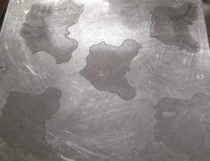
After printing, resin should be removed from the vat to ensure there are no fragments of cured resin in it before printing again, or if you need to change to a different resin to print.
1. Take your resin bottle used for the previous print, remove the cap and set up the funnel and a filter in its neck.
2. Carefully remove the vat with resin from the printer.
3. Tilt the vat towards the corner with the pouring spout and pour the resin through the filter and back into the bottle, be careful not to allow the filter to overflow.
4. Once most of the resin has been poured in, use the vat cleaning tool (squeegee) to guide the remaining resin to the corner of the vat.
5. Clean off any resin drips on the outside of the vat with paper towel.
6. Place vat on suitable clean, smooth surface (e.g. vat cleaning foam mat).
7. Use paper towel to soak up the last of the resin in the vat.
8. Use a small amount of IPA on paper towel to clean the vat film and vat walls, then let them dry them thoroughly.
9. Check for any fragments of cured resin remaining on the vat film, dislodge them with care using the soft spatula provided.
10. Give the outside of the vat a final clean and check the film for signs of damage or wear. Printing with a damaged vat will cause print failures and leaks and might cause a permanent damage to the printer. If you need to replace the vat film, check here for instructions. We recommend changing the vat film after 20 prints, this a list of the suggested maintenance procedures.
11. Check Magna screen protector for any sign of resin contamination or damage.
12. Store the resin vat in the printer when not in use.
Videos on how to replace the vat film, screen protector and suggested maintenace procedures can be found here
Cleaning the platform
After printed parts have been removed, it is vital that the print platform is cleaned thoroughly before being used again.
1. If any Photocentric Resin Cleaner or residual resin is left on the print platform, clean it off with IPA and a paper towel.
2. Cured resin should be removed from the platform using the scraper provided.
3. If you observe burrs or pickups on the platform indicate that you will need to be sand the platform bottom surface. The sanding should be gentle and with fine grit to avoid changing the platform form being parallel to the screen. Then, wipe with IPA and a paper towel.
4. Ensure there is no cured resin blocking the holes in the platform as this will affect future prints.
5. If available, use compressed air to remove loose debris from the platform to avoid piercing the vat film for future prints.
6. When not in use, the platform should be stored inside of the printer.
Cleaning prints
To remove residual resin from printed parts and platforms, clean the platform in a Photocentric Air Wash L.
For information on setting up and using the Air Wash L click here.
1. Free the platform by turning the knob anti-clockwise.
2. Grip the handles of the print platform securely and gently pull towards you to remove it. After removing the print platform from the printer, it is helpful to tilt and hold it over the vat to drain the excess resin. When carrying a finished print to your Air Wash L, use paper towel or a suitable tray to catch any drips.
Handle printed parts before post-exposure with care as they are more fragile as and avoid unnecessary exposure to light.
It is not recommended to take printed parts off the platform prior to the cleaning and post-curing steps. If removed, it may affect the dimensional accuracy of the parts.
3. Place the platform into the Air Wash L using the specially designed bracket.
4. Generally parts can be cleaned in 10 minutes using Photocentric Resin Cleaner 30. For some resins this may be quicker, refer to Photocentric Resins TDS for guidelines on wash cycle time recommendations.
5. Once the print has been washed, rinse using warm water to remove excess resin and solvent.
6. Photocentric highly recommends using compressed air to dry parts thoroughly. Alternatively, leave rinsed parts to dry before post curing.
Post-Curing prints
Parts produced using Liquid Crystal Magna will need to be post-cured using UV light and heat to fully deliver the correct material properties and leave the surface dry to touch. Photocentric recommends using the Photocentric Cure L2.
For information on setting up and using the Cure L2 click here.
1. Switch on the Cure L2 using the power switch at the front.
2. Set the desired time. Please refer to resin TDS for guidelines on time recommendations for curing here.
3. Set the desired temperature and allow the Cure L2 to reach the desired temperature.
4. Slot the print platform into the Cure L2 with parts facing down, ensuring that the handles slot into the attachment.
5. Press and hold the ‘Start’ button (up arrow). The timer will beep once the time has elapsed.
6. Remove the platform from the Cure L2.
Removing parts from platform
To remove parts from the print platform, Photocentric recommends submerging the hot print platform into cold water (thermal shocking) or manually removing parts via cutting or scraping. The chosen method will depend on the compatibility of the resin, accessibility of supports, and contact area of the part to the platform.
The print platform will be hot to the touch after the curing process. It is important to wear heat-resistant gloves when removing the platform from the cure unit.
- Thermal Shocking
1. Removing platform from the cure unit and immediately submerge the platform, just up to the part level, in cold water. It helps to add ice to it just beforehand.
2. Parts will pop off from the print platform or can be easily levered off.
- Manually Removing
If the resin type is not compatible for thermal shocking, use cutters to remove the supports from the part. Alternatively, use the provided scraper to remove supports from the feet. Scrape downwards to prevent damaging the parts.
After the parts have been removed from the print platform, fully remove the supports from the part and completely clean any artefacts form the platform.
Design guidelines
Design Specification
If you design a part with an understanding of how parts print on Magna you will end up with better functioning parts and benefit from more successful printing. These are only indications of what limits you should design within.
Individual geometries create different conditions of force at lift. Magna is equipped with patented Blow-Peel technology and low adhesion vat film which deliver incredible reliability and print performance. We recommend that you minimise the surface area per slice to avoid sudden significant change in surface area from one layer to another.
Parts cured on the platform will remain more accurate through to support removal. Flexible materials have lower green strength and need to be designed to be stronger.
All figures are resin dependant, high green strength means you can reduce these settings, high flexibility means you need to extend them. You can check design parameters on Resin’s TDS as well as we have created a summary for you in here.
If in doubt please ask us, we provide free design guidance to our customers.
Supported walls
Supported walls are connected to other walls and should be a minimum of 0.5mm for Rigid, Durable or Flexible resins to avoid warping. Add 0.2mm thickness for each 10mm increase in size. If 10×10=0.5 then 100×100=2.3mm
Unsupported walls
Unsupported walls are not connected to anything else and should be a minimum of 0.5 mm thick for Rigid, Durable or Flexible resins to avoid warping. Add 0.25mm thickness for each 10mm increase in size. If 10×10=0.5 then 100×100=2.75mm.
Supports and overhangs
An overhang refers to any part of a 3D model that extends outward horizontally or at an angle, unsupported by the layers below it. Overhangs can present challenges in printing because, without adequate support, they can droop or fail due to gravity during the printing process. Printing at 45◦ to the horizontal reduces lift forces. Overhangs that extend at angles less than 45 degrees relative to the vertical axis are generally easier to print without additional support, if they are taller than 100mm, then add supports.
Engraved features
Engraved details are recessed features on your model. A minimum depth and width of 0.8mm is required. It needs to be both deep and wide enough so it doesn’t fuse into the surrounding design.
Horizontal bridges
A horizontal bridge is the distance between two vertical structures. If the bridge is longer 3mm, then it may break during printing, or warp and lift off the platform.
Horizontal holes
Horizontal holes are those with their axis parallel to the XY plane. Minimum hole diameter should be 1mm for Rigid or Durable and 3mm for Flexible resins. Holes greater than 5mm diameter need supporting to prevent becoming oval.
Vertical holes
Vertical holes are holes with their axis parallel to the Z axis. Minimum hole diameter is 0.8mm for Rigid, Durable and 1mm for Flexible resins, but no deeper than 5mm. Holes should be designed larger by 0.15 to 0.2mm.
Connecting & moving parts
Clearance is the amount of distance needed between two moving parts of a model for instance between gears or joints. Parts should be printed separately and placed together after curing. For Rigid or Durable resins 0.15mm to 0.2mm for a tight fit and 0.4mm for a loose fit, For Flexible resins 0.5mm to 1mm for a tight fit and 2mm if parts need to move in and out (this can vary depend on shape and thickness of the part)
Drain holes
When a model is hollowed, adding drain holes is essential to allow resin to escape during and after the printing process and prevent cupping effect. Min diameter of 5mm hole and 1x hole per each 16 cubic centimetres of hollow part is recommended.
Maximum wall thickness
Thickness of the wall of the model should be limited to maximum of 10 mm. Large wall thicknesses can lead to sludging. In this case the wait time must be adjusted manually to 15s if part is no thicker than 50mm or 30s if part is thicker than 50mm.
Minimum wall thickness
For Rigid or Durable, min wall thickness for hollow parts is 2mm and for Flexible is 3mm. Adding internal infill is required. Large flat parts may need the addition of ribs or lattices to avoid warpage.
Pin diameter
A pin has a length greater than twice its width. At 0.8 mm thickness you can print up to 10 mm tall and it will remain straight. Minimum pin diameter for Rigid or Durable resins is 0.5mm, increase thickness by 0.25mm for every 10mm. For Flexible resins its 0.7mm, increase thickness by 0.35mm for every 10mm.
How to design for DuraGlide vat film:
DuraGlide film is thicker than 100microns FEP, however it has the same printability as 100 microns FEP.
Industrial Parts
Due to the enhanced peel release performance large parts can show an overall scanned accuracy greater in comparison to printing with 100 microns FEP. Due to its greater thickness fine features and details may become slightly bolder and dimensionally bigger by about 120-150 microns.
If printing parts with features that need mating, adjust the dimensions in CAD according to:
- Dimensions along x-axis:
- Male - reduce by 300 microns
- Female - increase by 300 microns
- Dimension along y-axis:
- Male - reduce by 300 microns
- Female - increase by 300 microns
- Pins radiuses reduce by 150 microns
- Holes radiuses increase by 150 microns
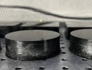
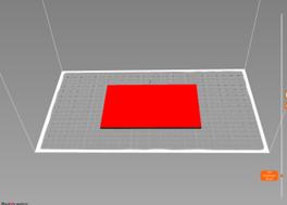
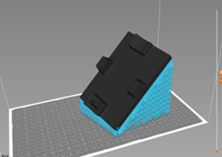
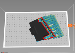
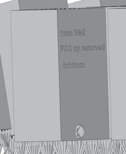
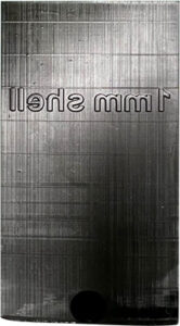
This example explains the adjustments. We have amended a test geometry’s features according to the design guidelines (Figure 5). Then, we printed with Durable DL110H - Black on Magna with DuraGlide vat film (Table.1).
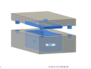

Table 1. Test geometry dimension amendments and results

For dental model printing for aligners, if the required scanned data accuracy is 80%<100um or less then we do not recommend using DuraGlide vat film.
Supporting parts
Supporting and orientating parts
The optimal orientation and support structure for a part is influenced by several factors, primarily its geometry, but also resin type and which surface you wish to be free from support artefacts. There are established guidelines for how you angle and support parts of varied geometries available in Photocentric Studio.
As a Photocentric customer you have our team of Design for Additive Manufacture experts available to help you optimise your manufacturing process.
If you want to optimise your digital mass manufacturing, contact the experts.
Maintaining Magna
Maintenance schedule
Task |
Frequency |
Instructions |
| Check the vat film whilst resin inside (with a squeegee) | After every print | |
| Filter resin | After every second print | Watch Video > |
| Clean the vat film | After every second print or when resin vat gets emptied | Watch Video > |
| Check/change blow-peel gasket | Every 100µm vat film change or monthly | Watch Video > |
| Check screen protector and clean if needed | After every second print or before placing vat back | Watch Video > |
| Clean platform | After every print | Watch Video > |
| Change vat film | 20 prints or after damage | Watch Video > |
| Clean fan filters | Monthly | Magna V1: Watch Video > Magna V2: Watch Video > |
| Check ball screws and rails for signs of oxidation | Every 6 months | |
| Replace LCD screen protector | After damage | Watch Video > |
| Check platform calibration | Only if instructed by Photocentric Support Team | Watch Video > |
| LED array, glass and fan cleaning | Every 3-6 months, depending on the room's environment |
Maintenance schedule
Check the vat film whilst resin inside (with a squeegee)
After every print
Filter resin
After every second print
Watch Video >
Clean vat film
After every second print or when resin vat gets emptied
Watch Video >
Check/change blow-peel gasket
Every 100µm vat film change or monthly
Watch Video >
Check screen protector and clean if needed
After every second print or before placing vat back
Watch Video >
Clean platform
After every print
Watch Video >
Change vat film
20 prints or after damage
Watch Video >
Replace LCD screen protector
After damage
Watch Video >
Clean fan filters
Monthly
Magna V1: Watch Video >
Magna V2: Watch Video >
Check ball screws and rails for signs of oxidation
Every 6 months
Check platform calibration
After print failure and advice from Photocentric Support
Watch Video >
LED array, glass and fan cleaning
Every 3-6 months, depending on the room's environment
Platform
- Interchanging platforms
Platforms can be interchanged between printers. They are not consumables but do wear out eventually. Print platforms should be sanded very carefully, using 60 grit sanding paper gently and evenly to ensure they remain flat.
- Recalibrating platforms
If a print failure occurs and Photocentric Service team advises to re-calibrate your platform, you can see how it is done below. We strongly advise you against calibration the platform if it is not needed.

Vat film
- Reskinning the vat
Vat film re-skinning should be done with the film provided if possible using the same screws. In case, it is needed to replace the screws, some spare screws are provided with accessories box. To reskin the vat film follow the instructions below.
You will need the following; Vat cleaning foam mat, Paper towel, Cleaning solvent (e.g. Isopropyl Alcohol), Scraper, 1 x Vat Film, 1 x Vat Gasket, Pozi 1 Screwdriver, Pozi 2 Screwdriver

- When to change vat film
The vat film should last for at least 20 prints. The life of the vat film will depend upon many factors including the surface area being printed and the viscosity of the resin.
How to reskin Magna vat film with a DuraGlide film
Reskin your Magna vat with DuraGlide film so that the glossy side will be in contact with the resin (inside) and the matt side will be in contact with the screen protector (outside the vat).
DuraGlide vat film is supplied with a blue cover film over the glossy side. The blue cover film needs to be peeled off before reskinning the vat.

Figure 1: DuraGlide vat film cover over glossy side
Follow the standard Magna vat reskining process:
https://www.youtube.com/watch?v=lnWq-t9uLTY
While considering below points: (Note: We recommend to change the blow peel gasket every 50 prints)
 |
 |
 |
| Figure 2. Bottom vat ring with countersinks facing upwards | Figure 3. Glossy side next to the bottom vat ring | Figure 4. Top vat ring over the matt side |
- Checking or replacing vat clamps
It is important to check and if needed to replace the vat clamps. Vat clamps securely holds the vat down which contributes to a consistent print performance. This is how to check or replace the Magna vat clamps:

Resin
- How to dispose of liquid resin
Resin waste may be polymerised in sunlight if the saturation level is high enough. In this case it can be disposed of as solid waste in land fill or burned. To get to saturation levels where polymerisation can be initiated, you will need to run a three tank wash system where you cycle the tanks from clean, to dirty, to saturated, the first tank, removes resin, the second washes and the third removes dirty resin cleaner.
Liquid resin cleaner and polymer will need to be collected for specialised disposal.
Troubleshooting Magna
File Upload
- File on USB is not recognised
To load the file from a stick, the USB must be formatted to FAT32 format, this is the only format the printer will detect. Do not load the file from a server, instead save the file locally on your PC. Ensure that your firewall is disabled, as it may prevent connection. Refresh the page on the user interface to check the uploaded file is present.
- Printer IP changes
Check the Wi-Fi router is not set to a dynamic IP, in which case the printer is allocated with a new IP address every time. Try connecting using this online file transfer method. Ensure the printer and the PC are connected to the same network that you are extracting the file from, and that the file is saved locally on your PC instead of on a server.
Platform
- Recalibrating the platform
If any print failure occurs and the Photocentric Service team advises you to re-calibrate your platform, you can see how to do it here: We strongly advise you against calibration the platform if it is not needed.
- Platform doesn’t move
On the GUI press 'Maintain' and then 'Lift platform' to see if motor will lift normally. If it makes a rattling noise and doesn’t lift the platform then please contact support@photocentric.co.uk.
User interface - GUI freezes
Magna v.1- Check the printer icon in the top left-hand corner of GUI, it should be in green colour when the printer is enabled. If the icon is red then it means the printer is disabled and won`t be able to function. Press the printer icon to enable it. Check if the printer is operating on the correct software / firmware on both the PCB and Pi.
Door Sensor
Check if the printer is running the latest version of the software. Go to our website and check the version you have installed is current, if not download it. Open the door and check if the switch is not damaged.
Screen - No image displayed
If no image is displayed on the LCD screen press 'Maintain' on the GUI and then '4K Display' to see if the LCD screen is showing the image or not. If the logo is not displayed, then please contact support@photocentric.co.uk
Vat leak sensor
The loud tone signifies that the vat leak sensors then the blow peel sensors have been activated, suggesting a vat leak. Vat leaks are caused when the vat film has been pierced by fragments of printed parts being forced into the base of vat. Resin then flows under the film entering the four channels in the blow-peel system as the air is evacuated in the air return cycle. The senor then stops the print process and prevents more resin from entering the Blow-Peel system. This is a vital operation to prevent damage to the machine. The sensors activate and sound the alarm. This video shows how to clean up after a vat leak:

If resin has cured inside the sensor, the beeping sound will continue after cleaning. You then need to remove the faulty sensor. To access them you need to open the side panels and disconnect the sensors one at a time to identify the faulty sensor. This video shows you how to remove and replace the sensors

Once you have identified the faulty sensor, tell us and we will ship you a replacement. This shows how to clean up resin spillages from the screen protector.

Once everything is complete and the system is up and ready, please run the vat leak sensor functionality test to ensure everything is plugged in correctly.
Blow peel doesn't operate
On the GUI press 'Maintain' and then press 'Pump' to do test and see if it holds the air between the screen plate and vat film. If it deflates then remove the resin vat and check the blow peel gasket is sitting flat on the screen. Check if there are no holes in the vat. Check the air pipes for a loose connection.

Photocentric Studio
- Lost License Key
If you’ve misplaced the license key, visit our website here and purchase the license key reset.
- Activating Studio license on a different system
To transfer your studio license to a different system, you need to first deactivate the license on your current system. Open the software and navigate to the ’Help' tab. Select the option to remove the license from the current system. This action will deactivate the license on that computer, this process requires an active internet connection.
How to increase the speed of printing with Magna?
Print with thicker layer thickness and use the variable layer thickness option for the area where surface finish is important.
If the wall thickness of the parts does not exceed 10mm, such as Dental Custom Trays, Casts (Splints), Lampshades, Face Shields, etc Magna v.2 fast printing profile can be used.
Diagnosing print defects
Nothing attached to platform
Appearance:
Nothing has printed on the platform and the part remains sitting in the vat submerged in resin.
Causes:
Software- part is positioned above the platform in the slicing software.
Platform- is too smooth or not homed correctly.
Reaction too slow- resin cold or exposure time too short.
Troubleshooting:
Software- To check your file is starting at the correct z-height on the platform, you can visually step through the first layers by moving the slice slider on the right side of your preview window with the shortcut PgUP and PgDN buttons on your keyboard.
Platform- If the platform has become too smooth it may no longer attach to the polymer. Take a fine (40 grit) sandpaper and rub it in a circular motion on the surface to deliver a key.
If it is not homed correctly, it may be starting the print above the LCD screen, rehome following these instructions here
Reaction too slow- Check you have heated the resin up before filling in the vat as some grades are less reactive at low temperatures than others. 35C is a good temp to start a print at.
Check the correct resin setting has been selected for the grade you are using.
Base layers only
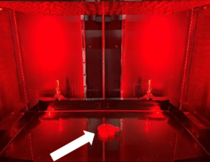
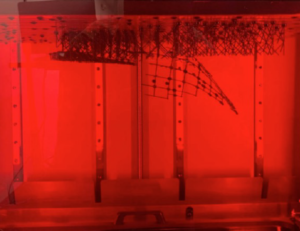
Appearance:
Only the first base layers have been formed attached to the platform, the rest of the print (arrow) is in the vat.
Causes:
Reaction too slow- resin too cold or exposure time too short.
Blow Peel is not working- Blow Peel gasket is damaged and leaking air.
Troubleshooting:
Reaction too slow- Check you have heated the resin up before filling in the vat as some grades are less reactive at low temperatures than others. 35C is a good temp to start a print at. Check the correct resin setting has been selected for the grade you are using.
Blow Peel is not working- Check by running a blow peel test, follow the video instructions here.
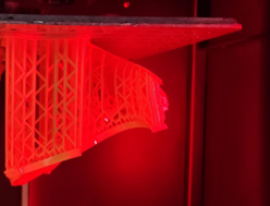
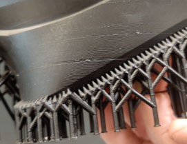
Supports only
Appearance:
Only supports are formed with the main part sitting in the vat.
Causes:
Wrong support profile selected.
Support tip diameter too small.
Under curing caused by wrong resin profile
Blow Peel failure.
Troubleshooting:
Wrong support profile selected- if it is too narrow or sparsely distributed it wont be strong enough to support the part, check our design guidelines here
Support tip diameter too small- if it is too small it wont be strong enough to support the part, each material has minimal feature size that it can hold. Check our design guidelines here
Under curing caused by wrong resin profile- each type of material has different exposure time. If you slice file with wrong profile the exposure time may not be long enough to form the supports and the model will fail.
Blow Peel failure– check by running a blow peel test, follow the video instructions here. If Blow peel stop working during the printing process, peel force may be big enough to pull model off the supports. On the GUI press ‘Maintain’ and then press ‘Pump’ to do test and see if it holds the air between the screen plate and vat film. If it deflates then remove the resin vat and check the blow peel gasket is sitting flat on the screen. Check if there are no holes in the vat. Check the air pipes for a loose connection.
Part breaks later in the build
Appearance:
The part is perfectly formed only to a level, the rest of the print is in the vat.
Causes:
Electricity stopped- power cut during the print
Slice missing in file- from mesh error
Part has structural design weakness- either supports or the object itself aren’t present
Vat leak - resin is under the vat
Blow Peel not working– Blow Peel gasket did not sit correctly
Debris in the vat– large solid particles in the resin
Troubleshooting:
Electricity stopped- check you didn’t have a power cut, the print would not restart.
Slice missing in file- check your file is complete and there are no blank image files at around where the break happens by stepping through the layers around where it failed, by moving the slice slider on the right side of your preview window with the shortcut PgUP and PgDN buttons on your keyboard you will see if there is a file with a blank slice in it (ie no or a significantly reduced amount of white pixels). If there is remove it or correct it.
Check part list if there is a mesh error notification on front of any part. If there is any, use mesh repair tools to fix the part ![]()
Part has structural weakness in design- check the part doesn’t have a large change in the cross-sectional area at around the height it ceased to build, if it does re-position it at an angle and support it more densely.
Vat leak- check there isn’t any resin under the vat. If there is change the vat film https://photocentricgroup.com/liquid-crystal-magna-resource-hub/
Blow Peel not working- check by running a blow peel test, follow the video instructions here. On the GUI press ‘Maintain’ and then press ‘Pump’ to do test and see if it holds the air between the screen plate and vat film. If it deflates then remove the resin vat and check the blow peel gasket is sitting flat on the screen. Check if there are no holes in the vat. Check the air pipes for a loose connection.
Debris in the vat- large solid particles in the vat can cause the next layer to not be able to start at the correct height. Filter resin back into the bottle, clean vat with IPA. Clean platform, take care to ensure there are no solid particles left in the holes or on the upper side of the platform.
Crack
Appearance:
Cracks are a break in the part, either created during printing or after post exposure.
Causes:
Large amount of mass which shrinks by more than a smaller mass, then the only way it can neutralise the force is to pull apart.
High infill or internal support density.
Unsupported islands inside hollow parts.
Troubleshooting:
Large amount of mass which shrinks by more than a smaller mass- Avoid sudden surface area change during the print, orientate your part in 45-degree angle if possible. Support your file with external supports, then hollow and then add the infill. Do not hollow first or the software will automatically generate internal supports in the voids.
High infill or internal support density- There are many different lattice structures, both geometric and organic that can maintain strength and minimise mass. Then add necessary drain holes to ensure that complex internally latticed structures can be washed thoroughly. Rinse and leave to dry for 4 hours before putting it in the curing unit.
Unsupported islands inside hollow parts- Check for islands inside the hollow cavity by clicking ‘’Show Islands’’ highlighted or use Slide bar to check the part. Manually support islands if necessary.
![]()
Warping
Appearance:
The part has twisted away from its intended shape.
Causes:
It is caused by the cumulative effect of shrinkage being distributed unevenly through the print.
Troubleshooting:
Eliminating warpage in every possible geometry requires experience, but it can always be achieved if you use a combination of:
- Orientate your part on the platform so that any rapid changes in area from slice to slice and moderated, this can mean positioning it a different angle to the vertical.
- Avoid sadden surface area change during the print.
- Use a lattice to replace solid elements, VoxelDance Additive software will ensure a strong lattice support network, reducing mass and therefore shrinkage.
- Using a dense network of external supports to hold the part in place during printing.
- Dry the parts thoroughly before post processing.
- Keeping the part with its supports on, still on the platform until after post processing.
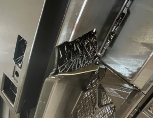
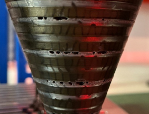
Vertical Line
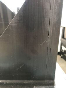
Appearance:
Vertical line that travels all way up the part.
Causes:
Screen failure creating a stuck line or a stuck pixel.
Troubleshooting:
Screen failure creating a stuck line or a stuck pixel- these are caused by huge peeling forces when print large solid flat objects that lift the screen and damage the ribbon cable. It is caused by printing large solid objects (over 30% of the screen area) and orientating them horizontally. To avoid it in future, orientated part at 45-degree angle and hollow the part if solid area is larger than 30x30mm for Hard materials, or 80x80mm for Durable materials.
Horizontal Line
Appearance:
The part has a noticeable line in it that isn’t part of the design. It can extend to lead to a break at the outside of the part.
Causes:
Debris in vat causes the part to be positioned above the correct level at the next layer’s exposure.
Slice missing in print file.
Part design has significant structural weakness in its shape causing structural failure.
Vat film is too lose and doesn’t disengage from the part fully at peel.
Weak support structure that isn’t strong enough to withstand forces during build.
Troubleshooting:
Debris in vat- these can be observed by tracing the line back to the start of the error where you should find the chip of polymer sticking out. Filter resin back into the bottle, clean vat with IPA. Clean platform, take care to ensure there are no solid particles left in the holes or on the upper side of the platform.
Slice missing in file- check your file is complete and there are no blank image files at around where the break happens by stepping through the layers around where it failed, by moving the slice slider on the right side of your preview window with the shortcut PgUP and PgDN buttons on your keyboard you will see if there is a file with a blank slice in it (ie no or a significantly reduced amount of white pixels). If there is remove it or correct it.
Check part list if there is a Mesh error notification on front of any part. If there is any, use mesh repair tools to fix the part. ![]()
Part has large structural weakness in design- check the part doesn’t have a large change in the cross-sectional area at around the height of the line. Sudden changes in the surface area create uneven shrinkage, with the tension only being released by the part separating at that level. To reduce this, orientate the part at 45 degrees to the xy axis and avoid the presence of large overhangs. Failure to support the part adequately will mean that newly formed large areas will shift away and cause misalignment at that layer.
Vat film is too lose – make sure vat film has no visible creasing and isn’t too floppy. Change the vat film every 30 prints to maintain the correct film tension.
Weak support structure- ensure it is strong enough to withstand from any movement during the peeling and gravity force. If model has too few supports or the support diameter is smaller than recommended, the model can move or shift during the print, which will cause lines, layer shifting or delamination. Follow the Photocentric design guidelines for supporting parts here
Cupping
Appearance:
Cupping, or a blowout, is a hole in the side wall of a spherical object.
Causes:
Cupping is caused when a hollow or convex portion of a part acts as a suction cup and traps air while printing. In printing a cup when the build platform pulls away from the screen during the peel process, the empty space within the cup increases its size and reduces the pressure within the cup to push the wall inward.
Troubleshooting:
Cupping tends to be more pronounced with resins that have low green strength or higher viscosity. It is evident in perfectly spherical shapes, large cup-like designs, or ones with very thin walls.
To minimize cupping:
- Orient the part to print at an 45-degree angle.
- Add a blow hole at the bottom of the design.
- Increase the wall thickness.
Consult the design guidelines recommended for your specific material and printer model here
Sludging
Appearance:
There is excess cured resin attached to the part and a puddle of soft cured resin the vat.
Causes:
Over-exposure of the resin with the resin moving while still curing. It is most visible in large solid objects above 30x30mm.
Troubleshooting:
It is caused by having resin that is too hot or the dwell cycle too short. If the part is larger than an area of 30x30mm it must be hollowed or orientated in angle. The larger the surface area the longer the delay time necessary, extend the ‘Delay time’ in ‘Print Settings’. Do not exceed a single solid area larger than 20,000 mm2 and do not use a solid boundary box size larger than 200x122mm. If the model is larger than these dimensions you must hollow or lattice the model.
Line formed on part 20-30mm from start
Appearance:
Causes:
This line is caused by the suction forces during printing when the part breaks above the level of resin in the vat, with no way of releasing the pressure. The hole in the base doesn’t release air pressure when it breaks the level of resin in the vat.
Troubleshooting:
Add a hole in the side wall to allow air to come in and out.
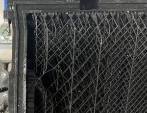
Creases on the printed parts
Appearance:
Causes:
Vat film is loose, and vat needs to be re-skinned.
Troubleshooting:
Reskinning the vat film by following the instructions here
Photocentric Air Wash L
Installation and set-up
Choose a flat stable location with enough space for the unit and leave extra room over the unit to allow opening the lid.
The installation location should have an operating temperature in the range 18-28 °C. Operate in a low-light or red lighted work environment as resin will cure in ambient light, always avoid direct sunlight. Use Photocentric Air Wash L in a well-ventilated area, we recommend using direct extraction via the duct. To connect the Air Wash L to extraction, use a screwdriver to open the vent on the top of the unit and fasten a 4-inch spigot, purchased separately.

Unboxing Air Wash L
Air Wash L is packed in a cardboard enclosure. Do not lift the unit, as it weighs 56kg (124lbs). To unbox Air Wash L, remove the plastic packaging and remove the cardboard sleeve covering the unit. Check that the caster brakes are not locked, slide the unit out of the cardboard base, on its casters, and place it on the desired location. Two people are recommended for this operation. Use safety gloves with a secure grip surface to prevent slipping. When in the correct location, press caster brakes to ensure stability of the unit while operating.
Power Requirements
Air Wash L requires an earthed mains power supply with a voltage of 110VAC or 220VAC and its power consumption is rated at 35-45 watts. Only connect Photocentric Air Wash L to the mains socket using the power cable supplied. The wash unit power cable is on the right-hand side of the machine. Always plug the power cable into the mains socket and into the wash unit before switching on the power at the mains socket. Similarly, always switch off the power at the mains socket before unplugging the power cable from either the wash unit or the mains socket.
Extraction
Always use Air Wash L in a well-ventilated area. We recommend using the Bofa extraction unit, more information can be found here.
To connect the Air Wash L to extraction, use a screwdriver to open the vent on the top of the unit and fasten a 4-inch spigot (purchased separately), which can be linked to the extraction duct. An example for the spigot can be found here.
Air Wash L set-up
Open the lid and lift out the support bracket. The basket is asymmetrical due to an incline at the base, ensure the longer legs are situated on the left-hand side of the unit. Add Photocentric Cleaner to the ‘Maximum Level’ marker. Plug the machine into the mains supply socket. Replace the support bracket.
Operating Air Wash L
1. Ensure the lid of the wash unit is opened before removing the platform from the printer.
2. Remove the platform from the printer by turning the knob in an anti-clockwise direction and gripping the handles.
3. Allow excess resin to drain over the vat before removing that platform from the printer.
4. Hold the platform over the open wash tank and apply the bracket centrally underneath the platform location plate.
5. Carefully lower the platform into the wash unit, locating the support bracket over the tank width.
6. Close the lid and press the power button to start the wash unit, refer to resin TDS for information on wash times.
7. Once the cycle is complete, press the power button at the front of the machine to switch it off. Do not leave the platform in the resin cleaner for longer than stated on the resin TDS as it may have an adverse effect on the parts.
8. Lift the platform out of the wash tank and remove the bracket. This can be placed back into the wash tank in preparation for its next use.
9. Tilt the platform over the wash tank to allow excess resin cleaner to drain.
10. Close the lid of the wash unit and transfer the platform to the sink and rinse the parts with warm water.
11. Dry the parts with compressed air or if not available leave to dry naturally before post curing.
When to change resin cleaner
Resin cleaner gradually becomes saturated with resin and gradually becomes less effective. Use a hydrometer to read the density and when it reaches 1.02 change your resin cleaner. The process is specified here
To clean the wash unit, make sure it is powered off and disconnected from the mains. Connect a suitable pipe to the drain valve and allow the used chemical to flow into a suitable container for disposal which should be collection from a recognised waste disposal agency in accordance with your local regulations see the Cleaner Safety Data Sheet.
The drain valve inner diameter is 30mm, recommended materials for the pipe are EPDM, EPM and NR.
When you have drained the solvent, you can see that the tank has an incline at the base. Remove any residual debris collected here for safe disposal. If a build-up of resin is observed on the air bars, use a 14mm spanner to remove the two nuts securing the assembly to the tank. Remove the assembly and clean thoroughly, re-fit in reverse, ensuring that the holes are facing down.
After cleaning, ensure the drain valve is closed off before adding fresh solvent to the wash unit.
You can download the user manual here.
Photocentric Cure L2

1. On Off switch
2. Internal Fan
3. Temperature unit
4. Temperature adjustment
5. Timer controller
6. Timer adjustment
7. Hanging bracket
8. Heater unit
9. Door seal
10. Rear light
11. Bottom light
12. Glass shelf

1. On Off switch
2. Internal Fan
3. Temperature unit
4. Temperature adjustment
5. Timer controller
6. Timer adjustment
7. Hanging bracket
8. Heater unit
9. Door seal
10. Rear light
11. Bottom light
12. Glass shelf
Installation and set-up
Choose a suitable location for your Photocentric Cure L2, allowing plenty of space see below. It has external dimensions of 500 (W) x 350 (D) x 550 (H) mm and can accommodate parts up to 220mm in height.

Dimensions are in millimetres
Unboxing your Cure L2
Remove the outer packaging and recycle it. The Cure L2 weighs 64 kg (141 lbs) so lift it with equipment or enough people (we recommend four). Allow space to open the door. work and remove any potential obstructions. Use gloves and follow safe lifting practice. Always use Photocentric Cure L2 in a well-ventilated area.
Power requirements
Photocentric Cure L2 requires an earthed mains power supply with a voltage of 110VAC – 240VAC and a frequency of 50 Hz – 60 Hz. It has a power consumption of 1000W. It will draw a current of 4A when connected to a 240VAC supply, or 9A when connected to a 100VAC supply. Connect Photocentric Cure L2 to the mains socket using the power cable supplied. Always plug the power cable into the mains socket and the cure unit before switching on the power at the mains socket. Similarly, always switch off the power at the mains socket before unplugging the power cable from either the cure unit or the mains socket. The cure unit power socket is on the back of the machine on the right side. The power switch is on the front, top left.
Operating Cure L2
The unit temperature is factory set to 60°C (also the maximum temperature). To set the temperature for the curing programme, press the ‘Set’ button on the temperature control then using the arrows, select the desired temperature. When the selection is complete, press the ‘Set’ button again. Once the desired temperature is displayed, set the time.

Hold the ‘Set’ button on the time controller panel and amend using the arrows to reach the desired time for the curing programme. Refer to Resins TDS to find the desired time. Press the ‘Set’ button again to confirm your selection.
1. Switch the cure unit on using the power button at the top left of the machine. Once on, it will illuminate.
2. Set the desired curing cycle, using the time and temperature controllers. Allow enough time for the cure unit to reach the set temperature before loading any parts (typically between 5 and 15 mins).
3.Once the parts and platform have been washed, rinsed and dried, transfer them to the cure unit.
4. Open the door of the cure unit using the safety latch on the right-hand side and load the print platform onto the hanging bracket.
5. Close the door and secure using the safety latch.
6. Press and hold the ‘Up’ arrow on the time controller to begin the cycle. The display will start flashing. The cure unit will not operate if the door is open.
7. Once the curing cycle is complete, a continuous beep will sound. Switch off the cure unit using the power button.
8. Open the door of the unit, using heat resistant gloves, remove the print platform from the hanging bracket. Dependent on the recommendations on the resin TDS, either submerge the platform in cold water for thermal shocking or leave to cool before removing parts manually.
Maintenance
Before carrying out any of the below tasks, make sure the unit is at room temperature and has been disconnected from the mains power supply. Ensure that the inside of the machine is kept clean, especially the glass covering the UV lights. Check the condition of the door seal for heat retention. Check the integrity of the mains cable. Make sure the vents on top of the unit are not covered or filled with dust.
Technical & Application Guides
Dimensional Accuracy
Dimensional accuracy is a critical performance metric for any additive manufacturing platform. The Technical Note below outlines the factors that influence the accuracy, precision, and repeatability of parts printed on the LC Magna. It also details how LC Magna hardware, materials, and workflow contribute to consistent performance across the build volume.
The purpose is to equip our technical users with practical insights to achieve optimal results with LC Magna in demanding manufacturing environments.
Guidelines for Printing Props
Everything you need to know to make amazing props using LC Titan and Photocentric resins.
Guidelines for Casting
The following design rules will help achieve a successful and dimensionally accurate print and cast results, as part of preparing your CAD file ready for print.
Guidelines for Shoe Moulds
Printing shoe moulds with HighTemp DL401 resin & VoxelDance Additive software on Liquid Crystal Magna.
How to produce dental models on Magna
Watch the video below to learn how to produce dental models on your LC Magna. To view the guide click here

Photocentric Studio
Preparation of models in Photocentric Studio is one of the most important steps of the printing process and it is worth spending time to really understand how to support and orientate parts on your Magna printer. Note, this process may differ from other printers you have used.
Applying optimised supports and part orientation is critical to making parts within tolerance, obtaining excellent surface finish and achieving fast production times.
When orienting your parts think about:
- centre of gravity- this will change as your geometry changes through the print.
- suction - avoid a cupping effect by incorporating vent holes
- Peel forces- counter any pull downwards by angling the part to minimise the surface area per layer, aiming for a gradual increase in surface area.
- Supports are needed only when there is an overhang or a flat surface facing the platform.
- Surface finish- support the part in areas surface finish is not important and to minimse time spent removing supports.
General Rules for Orientation and Supports:
To achieve dimensional accuracy and to compensate for any shrinkage, we recommend scaling up the model in volume by 0.5% in all three axes (xyz).
Do this before slicing or set it as your default by opening your chosen resin profile, select the ‘Part pre processing’ tab and click on ‘Shrinkage correction scale XYZ’ to change values to 1.005 in all three axes (ie. Increasing the volume by 0.5%). Press ‘save’, then, every time you select this resin the scaling factor will be automatically applied.

Figure 1: Shrinkage Correction Scale
Positioning Models
Placing models too close to each other (such as when printing multiple copies of the same model) will adversely affect the surface quality of your parts and make washing the parts more difficult. It can also make achieving complete post processing on the platform harder as light will not be able to reach all areas evenly.
- Keep at least 3mm between parts. For black resins, the minimum distance between models should be 5mm.


Supporting Prints
When using supports, raise parts to a minimum height of 10 mm above the platform to allow:
- More complex support structures
- Easier part removal from the platform
- Easier support removal from the part
- When printing large surfaces, increase the height of supports to 20-30mm.
Minimum wall thickness
- for rigid resins such as High Tensile and Hard set it to 0.5mm
- for flexible resins such as Flexible set it to 2mm
Minimum support tip diameter
- for all rigid materials is 0.6mm
- for all flexible resins is 1.2mm
Tips & tricks for orientating models
Flat parts are better printed vertically

Flat models with large surface areas should not be printed flat, directly on the build platform or with short supports. Large surface areas attach too well to the platform and are easily damaged when removing them. In addition, resin flow will create a rough surface around the model. Printing flat and/or on short supports may cause the model to deform through shrinkage and takes longer to remove support material.

Flat models should be printed vertically. The model can then be placed directly on the build platform. Alternatively, lift the model 10mm above the build platform and support the bottom surface.
This orientation minimises the surface area requiring supports. The model will then look smooth from both sides and less time spent on removing supports.
Print at 45 degrees to the x, y and z axes

This model will have a rough surface on one face as the pixels shift across it. As it has only been orientated to the x axis.

To achieve a smooth surface finish and to avoid pixel shifting lines on flat surfaces, rotate your model to be 45 degrees to the x, y and z axes.
Angle boxes at 45 degrees to all axes and support 15mm off the platform

Just orienting large flat models in one or two axes will lead to deformation in the first few layers created by peeling forces and the change in centre of gravity.

Rotate flat or box-like large models at 45 degrees to all three axes and lift the model 15 mm from the platform.
This orientation results in a gradual increase in surface area, reducing the risk of warpage and anisotropic shrinkage in the printed model.
Printing vertically reduces the amount of supports necessary

Printing this part horizontally would need a lot of supports on the bottom surface, meaning longer file preparation and support removal in the post processing stage. The part could also deform without internal supports.

Orientating this type of model vertically will require fewer supports. The print will take longer than in a horizontal orientation, but you will save in less post processing and it will have a better surface finish.

Don’t print tubular shapes horizontally. The model will deform with the internal cavity changing from circular to oval. Adding internal supports can help to avoid deformation, however file preparation and post-processing time will increase.
Orienting this model at a 45 degree angle would require a lot of supports and extra post processing.

Support a tube vertically for best surface finish and dimensional accuracy. Lift the model by at least 10mm from the platform to avoid failure due to suction forces. Parts will also be easier to remove from the platform.
To support the parts, select the resin profile and then the correct support profile.
- Large Prints are up to 350mm Z height
- Medium Prints are up to 200mm Z height
- Small Prints are up to 100mm Z height

Tips & Tricks for Creating Support Structures
Click ’Support mode’ and choose.
![]()
This will automatically generate supports.
Always visually check all the critical areas have been supported.

If there are areas which require extra supports press
![]()
When you see the non-supported areas click on the areas that need reinforcing to add additional supports.
The distance between supports should be 2-3mm. An indicative measure is that the platform grid size is 5x5mm.
Once all of the critical areas are supported, press ![]()


Automatic supports do not always add supports to all critical areas. In this photo, supports on the bottom have only been added to one edge. This model will fail or deform in this area due to gravity and peeling forces.

When using automatic supports, always edit to add more supports as necessary. Supports need to be strong enough to hold the model and resist the pull of gravity and peel forces during printing. Supports must also be as close as possible to the edge of the model.

In some cases, automatic supports are not sufficient. In the above example, manual supports should be added to support the critical angles and make the structure strong enough to hold the part. If printed without extra supports, the part will fail or deform during printing.

This is an example of an optimised combination of automatic supports and manual adjustments. All critical angles are supported, the supports are evenly distributed and with the correct density.


Without supports on both edges, the first layers will start to deform, the edges will not be cleanly defined and print failure may result.

First layers are very important. Angled edges must be supported from both sides to keep a defined, sharp edge.

Positioning the part vertically over the plate, directly or on supports will cause the first few layers to deform and lead to warping.

If the model size and shape allows, orient it at an angle to all axes.


A distance between support tips of more than 3mm will lead to a rough surface where there are overhangs. Distances of more than 5mm will create deformation and delamination.

The distance between supports should be less than 2mm and as close to the edge as possible.

Support tips should be close to the edge.

If support tips are too far from the edge, the model will be rough and deformed.

Without internal supports, holes will deform and become oval in shape.

For round holes larger than 2mm in diameter add one internal support.

Support feet angled downwards as above will be harder to remove.

Adding support feet angled upwards as shown, will make part removal easier.


Don’t print large models flat. It will be very hard to remove them from the platform and they may break.
Printing this part as shown, with overhanging horizontal surfaces will require internal supports to avoid deformation. These would be extra post processing and give a poor surface finish.

Orientate this type of model vertically with no supports. Print time will be longer than orientating horizontally, but the part will need less post processing time and will subsequently have a better surface finish. Orientate parts with internal overhangs so they require minimum internal supports. The best option is to align this part with overhangs vertically to the build plate, giving the best surface finish on both sides.

If features overhang by more than 1mm and have sharp angles add supports to keep the edge sharp.

If features overhang by more than 2mm and have rounded angles add supports to keep the edge shape.

If overhangs are shorter than 2mm and are self-supporting on both sides, there is no need to add supports in the middle.
Hollowing
Photocentric Studio has an option to hollow large models (model geometry and application permitting).
Hollowing will reduce resin usage, hence print cost. It also reduces weight which can help improve the print quality and success rate.
Minimum wall thickness for ‘Investment Casting’ application is 0.5mm and for general large prototyping models is 2mm.

Once hollowing is complete, we recommend adding an infill structure to make models more rigid and to support internal overhangs.
Minimum infill diameter is 0.5mm for ‘Investment Casting’ parts, with cell size of 5mm.
Default settings are 1mm infill diameter and 5 mm cell size.

In 'Transparent View', you can check the infill structure.
Hollowing and infill can save up to 80% of resin while still keeping models rigid.
Hollow models need drain holes to reduce the suction effect during printing.
Choose ‘Flexible drainage hole’ ![]() in ‘Support’ mode.
in ‘Support’ mode.
Minimum drain hole diameter is 4 mm.


Without drain holes in hollow models eg, bottles, the force inside the model can break the wall or create visible lines across the whole model.

Hollow models need drain holes to be added. Drain holes reduce the suction cup effect during printing.
Example 1

If you orient this model with a sharp angle as shown here, it will lead to an unneccessarily long print time, more supports will need to be used giving an increased post processing time and you will have a poor surface finish.

The best orientation for a box-like model, is to lift the part from the plate by 10mm, rotate it around all three axes and support the bottom surface sufficiently.

Example 2

Automatically generated supports for a tablet case lid.

Edge sides are not properly supported and will be deformed during the print. The first few layers will warp and deform due to peeling forces and the lack of supports.

The automatic support function only recognises outer edges as overhangs and does not support internal surfaces which are still cititical areas.

Printing this model vertically with length or width parallel to the plate, will result in deformation in the first few layers. The top edge overhang may also deform. Where possible, follow the gradual build up rule, building from a smaller surface to a larger surface area gradually.

After applying automatic supports, manual supports on the internal surfaces are needed. Additional supports should be added, evenly spaced and covering all internal areas.

Optimised support structure after manual adjustments.

If you have enough space, we recommend printing this part vertically at an angle of 45 degrees to the platform.
Print time will be longer, but post processing time shorter, as internal surfaces are self-supported. Surface finish will also be better.
Make sure the part is lifted by 10mm from the plate.

Example 3

This is not a recommended orientation. Now all of the fins are overhangs and need supporting (automatic supports would not be enough). This orientation would create more work to support and to finish.

Think about how to minimise overhangs when considering print orientation. Here, the engine fins are kept intact with minimum post processing time, only needing supports on one side. You can also add some internal supports inside the cylinder.

To avoid deformation, print thin, flat surface areas vertically. If you orient this model at 45 degrees, the main body will print well, but the fins will deform slightly as they have not been supported enough to overcome peeling forces and gravity.

This is an optimised combination of using automatic supports at 5% density with manual support adjustments.

If positioned at a 45 degrees angle it is not possible to support fins sufficiently and after printing 2-3mm the fins will start to deform.

An overview of where manual support tips should be added.