
Photocentric Studio Pro Support
Setting Up Software
Minimum computer requirements
Operating System (OS)
• Windows 11 (64-bit)
• macOS (via Virtual Workstation running Windows)
• The software can run on macOS by using a Virtual Workstation (e.g., Parallels, VMware, VirtualBox) with Windows installed.
Processor
• Minimum: Dual-core 2.0 GHz
• Recommended: Quad-core or higher
• Memory (RAM) 64-bit systems: Minimum 8 GB
Graphics
• GPU supporting OpenGL 3.0 3 or higher
• Example: NVIDIA GeForce 1050 or better
You can run the software using macOS by using a Virtual Workstation with Windows installed on it.
License Activation
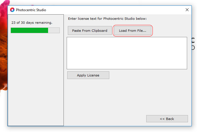
The program comes with a 30-day free full featured trial license. Each license can be activated on 1 or 2 PCs.
Activation
License activation requires an internet connection to validate your license. Please enter the license without any text/title/enters/newline/spaces. If you are not sure if your email program modified the license string you can always open the license in notepad to make sure there are no enters/spaces.
Installing a newer version
Installing a newer version of the program can be done without removing the license. Just uninstall the current version and install the new version. The license will stay in place.
Moving to another computer
You can move your license to another computer. Go to 'Help -> remove license' to remove the license and deactivate your computer. This requires internet connection. The program will close afterwards. Now you can activate your license on another computer.
Updating Photocentric Studio to Photocentric Studio Pro
Deactivate Your Current License
Go to the Help tab and select Remove License. Make sure to save your existing license key file in a secure location.

Activate Studio Pro
- Reopen the software and activate it using your Studio Pro license key.
- If you don’t have a Pro license or would like to try it first, please purchase a free trial license key here
- Check if pro features appear in UI if not you may need add them from tool bar option

Optimising Graphics Card Settings
Graphics cards are purpose built to handle 3D Graphics and applications, these are things that your CPU can have a hard time with as it was designed to run your operating system first and other functions secondarily. Most Windows computers are going to run Photocentric Studio off of your CPU by default, so its really important that you make some minor changes in your NVIDIA Control Panel to offload Photocentric Studio's 3D graphics processing to your NVIDIA GPU so that there are no worries about slowdowns and crashes.
Follow the steps below to change your graphics card settings:
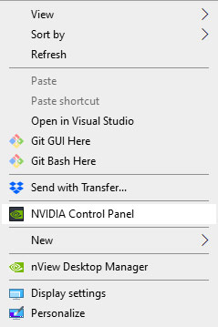
1) Right click on your desktop and select 'NVIDIA Control Panel'.
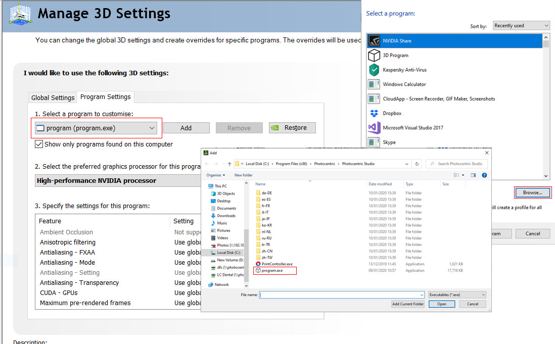
2) In the NVIDIA Control Panel select Manage 3D Settings at the top left. Select 'Program Settings' and add 'Photocentric Studio'. Click Add next to '1. Select a program to customize'.
If Photocentric Studio is not listed, in the 'Select a Program' pop up window select 'Browse'. When the next window pops up, on the left select the tab that says 'This PC'. From here select your 'Windows (C:)' Drive.
From your C Drive, select Program Files (x86) then scroll to and select Photocentric Studio folder and finally select the 'program .exe' file.
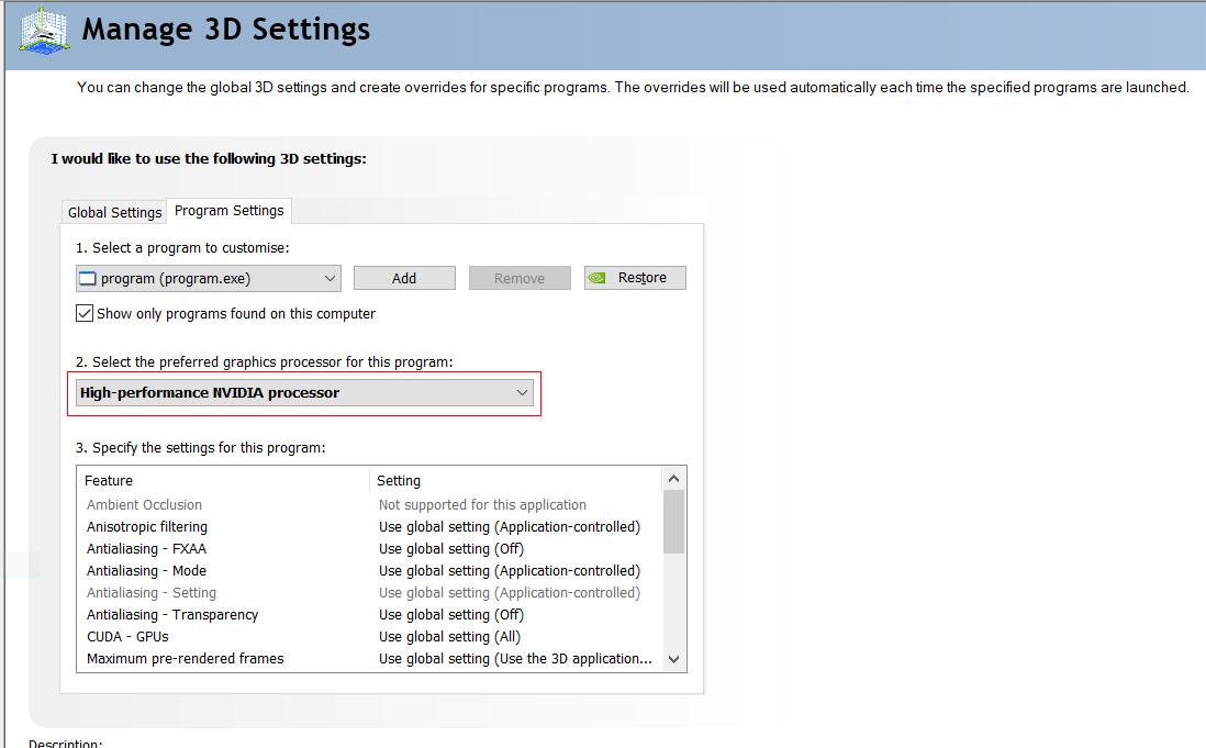
3) Once you've selected Photocentric Studio, in the drop down menu select your graphics card processor in this case, NVIDIA
Toolbars and Software Navigation
Layout
The menu bar at the top of your screen contains all the tools available to you during normal operation. Some of the menu items also have keyboard shortcuts. These are displayed in the menu item.
Toolbar
The toolbar is underneath the menu bar. (All the tools from the menu can also be found in the toolbar if you find this easier to use). When you hover over the toolbar icons, a description will popup. Note that when you enter different modes in the program (eg. supporting mode) different toolbar buttons will deactivate.

Tip: After any operation eg. supporting, rotating, scaling, copying, etc. remember to press “esc” to return to full normal mode.

Most options will be disabled (greyscaled out as shown) when working on a particular operation.
Switch between machines and profiles
Users can change the machine or resin profile at the start of the program, before slicing or during file preparation. The menu for machine and profiles is located at the top right - there are 2 selection boxes allowing you to change your machine (build table size) and your print profile (e.g. layer height).

This window also shows the estimated print time for your current layout, the volume of resin used and the number of layers. The time is calculated by multiplying the number of layers with the average layer time setting.
Tool Belt
Under the machine and material windows is a new tool belt. This useful additional tool bar can be fully customised to add a user’s most frequently used workflow features.
The tool belt can be edited in the configuration menu:

Here, the user can choose to switch User interface from basic to advanced, or can create a bespoke user interface by choosing functionality from the tool belt.

Advanced (full functionality)

Basic

Part and object information
The window above the tool belt shows the part name and details:

If you select the object, a pop-up window will appear with additional part details (volume, dimensions etc).
The following options allow you to make changes to your part:
![]() The eye symbol turns visibility on or off.
The eye symbol turns visibility on or off. ![]() The coloured circle allows you to change part colour.
The coloured circle allows you to change part colour.
![]() Some parts may show an exclamation mark on import. This means they might contain mesh errors. Further mesh diagnosis and mesh repairing using 3rd party software is required, e.g Microsoft 3d builder or online mesh repairing tools.
Some parts may show an exclamation mark on import. This means they might contain mesh errors. Further mesh diagnosis and mesh repairing using 3rd party software is required, e.g Microsoft 3d builder or online mesh repairing tools.
Tip: Right clicking (using the mouse) on the selected object will take you directly to the part.


Slice Bar
The slice bar in the 3D view allows you to see a cross section of your prepared slice job. Drag the bar to view a cross section. It can be configured to have 1 or 2 handles. 2 handles are recommended for advanced users only. 2 handles might be handy during supporting when you would like to clip the lower part of your model. 1 handle might be easier to simulate the print job and view the resulting cross sections.

Navigation and Camera
To operate in 3D, we recommend to use a computer mouse (left/right/wheel mouse buttons) and a keyboard, to help create a smooth and intuitive navigation. You can also use a 3D space mouse.
Rotation (Pitch & Yaw)
To rotate the window, hold down your right mouse button and move your mouse. You can roll vertically and horizontally. When the mouse reaches the end, it transfers to the other side of the window so you can continue rotating.
Translation (Panning)
Hold down shift and then hold down your right mouse button to translate (Pan) the view. Alternatively, you can pan holding down the mouse wheel. Panning always happens perpendicular to the viewing direction. If you pan from the top you move in XY plane. If you pan from the front you pan in XZ plane.
Zooming (to mouse)
You can use the mouse wheel to zoom your window. When you move your mouse, you will notice the view zooms. This allows you to inspect certain parts of your model more easily.
Viewing perspective
In the toolbar there are 5 blue cubes that change your viewing perspective. Ctrl + P is a useful shortcut for resetting your 3D View:
 Perspective view Ctrl + P
- Left view Ctrl + L
- Front view Ctrl + F
- Top view Ctrl + T
- Bottom view Ctrl + B
3D mouse
If you have a 3D Mouse from the Connexion brand you can control your view with the 3D Mouse. By default, it rotates your object (the build table) in 'object mode' which means that it feels like the build table is in your hand and you are looking at it. There are several settings under the configuration menu for the 3D Mouse.
View modes
The program features 4 different view modes
 Shaded: draws only the surface without borders F5
 - Wireframe: draws only the triangle borders F6
- Filled frame draws the mesh including all triangles. F7
- Transparent: draws the mesh transparent. In this mode you can only select supports/infills/holes etc. but not the mesh itself. This helps you to select difficult to select parts. After several commands (hollowing/infill) the program switches to transparent view mode in order to show you the generated features. F8
Preview options in the top tool bar
At the bottom of the screen are a couple of interface helper functions that can be toggled on or off. With the ![]() and
and ![]() icons below it, you can toggle to fill in the cross section or to leave it empty and look inside your mesh. Please note that when you clip your model from 2 sides with the slice trackbar it will become transparent automatically.
icons below it, you can toggle to fill in the cross section or to leave it empty and look inside your mesh. Please note that when you clip your model from 2 sides with the slice trackbar it will become transparent automatically.
The ![]() icon toggles the grid snap. Grid snap means that when dragging objects, they will snap to an invisible grid. You can define more grid snap settings in the configuration.
icon toggles the grid snap. Grid snap means that when dragging objects, they will snap to an invisible grid. You can define more grid snap settings in the configuration.
The ![]() icon helps you visualize the cross section on your object by a white line. Using this in supporting mode makes it easy to place supports at the same height.
icon helps you visualize the cross section on your object by a white line. Using this in supporting mode makes it easy to place supports at the same height.
With the ![]() icon you can quickly enable or disable visibility of the critical build areas on your parts. You can also find this setting in the configuration window.
icon you can quickly enable or disable visibility of the critical build areas on your parts. You can also find this setting in the configuration window.
Each support algorithm uses a different filter for critical minima and some minima might become unsupported in the process. In order to view critical minima after a model is supported, use this ![]() toggle.
toggle.
File Opening and Batch Processing
Difference between New/Import/Open
- 'New' will open a blank file. It will first check if you would like to save previous work.
- 'Open' will open any selected file into a new workspace. It will first check if you would like to save your previous work. This is like 'New file'.
 'Import' will import any file into the existing workspace.
Supported File Formats (opening/importing)
stl - (Stereolithography file) The standard file for 3d printing. Binary stl files open significantly faster due to faster reading.
stl compact (stlc)- a custom binary format that is the most efficient way of storing geometry in terms of storage space. Can be used when transferring files very large files to another pc.
ply (Polygon file format) - Used in some 3d scanners & in the dental industry.
amf (Additive manufacturing file format) - A zipped xml format.
slc (Slice file) - A binary file consisting of 2D Curves at different Z levels. Can be converted to PNG slices after import or alternatively it can be converted to a mesh.
obj (Wave front .obj file) - Used in the animation industry. When importing them, the program only reads the triangles. Other polygons are converted back to 1 or multiple triangles. Textures are ignored.
p3d (The program's own project files) - project files are files which contain objects and supports created by the software. You can use this to open previous print jobs to edit/process them again.
svg (Standard vector graphics). Svg is an ascii file format to store coordinates. It might be handy to view what you are exporting. Some machines require Svg files. This can be either all layers in 1 file or one file per layer. You can import 1 file at a time.
Import file special
Some files may need to be imported in a particular way. In order to keep normal imports simple, we've separated these out in a special import menu. Currently, the following special imports are available:
- Materialise magics thin supports: this import option allows you to import Materialise Magics generated support structures that have 0 thickness. The program will ask you to give a value and will then generate a thickness for the support parts.

Batch processing
![]() The batch processor gives you the ability to prepare multiple files for printing at the same time. It gives you the following options:
The batch processor gives you the ability to prepare multiple files for printing at the same time. It gives you the following options:
- Copy amount: if different to 1, the part will be copied.
- Auto orientation: choose a way of auto orienting your parts.
- Support profile: pick any of your defined automatic support profiles. You can also leave them unsupported.
- Auto layout: nest your parts on the build plate with the selected algorithm.
- Rectangular nesting is fast for simple geometrical shapes. Irregular nesting is advanced and use build plate available space more optimally. However, it takes longer for processing comparing to Rectangular nesting.
Handling large stl files
The program is tested for .stl files up to 500mb. Larger files may result in unstable behaviour. We've put together some tips to avoid large .stl files.
- Only export. stl’s from your CAD package in a resolution that your Photocentric 3d printer supports, 400 MB. Any more detail might add unnecessary size to your file.
- Don't try to import all your models as 1 .stl file. Import as single files and then nest your build job in this program.
- Use tools like 'Reduce Mesh' in Rhino3D or similar CAD programs to reduce the size of your mesh. Usually, they come with 'accuracy' settings that can prevent changes in geometry.
- Make sure you are using binary. stl’s. These take up a lot less memory.
Project File and Files Saving
Options for savings
- 'Export selected' will only export selected objects
- 'Save' will save to the currently open file location (visible in title bar)
- 'Save as' allows you to choose save location
- 'Export to program as. stl' will show you a list of available programs that can open .stl files. You can export your work directly.
Saving/export as stl and as a project file
stl - (Stereolithography file) The standard file for 3d printing. The program can export to binary or ascii stl format. Supports can be exported as a separate file or joined to the part.
stl compact - a custom binary format that is the most efficient way of storing geometry in terms of storage space. Can be used when transferring very large files to another pc.
p3d project file - (The program's own project files) Project files contain the entire structure of created objects. Use this if you want to continue working on a print job later i.e. edit supports reorient models, add more models.
Orientating & Sizing Models
Large surface area detection
Avoid large surface area highlighted in violet, try to orientate your part by minimizing these areas.


This software provides multiple options to orient your objects. They are available under icons in the tool bar and toolbelt, and are described in detail below.
Manual movement and rotation using gumball tool

Move to 0, 5 or 10 mm
![]()
![]()
![]() These buttons allow you to quickly move your object to a fixed height from the build platform. You can use absolute translation if you need another specific amount.
These buttons allow you to quickly move your object to a fixed height from the build platform. You can use absolute translation if you need another specific amount.
Centring
![]() This centres the selection on your build table and on z=0
This centres the selection on your build table and on z=0
Translations
![]() You can add relative translations or translate your selection to an absolute position.
You can add relative translations or translate your selection to an absolute position.
Rotations
You can add rotations to the selected objects in 3 different axes.

Scaling
![]() There are 3 options for scaling.
There are 3 options for scaling.
- Scale factor: this allows you to scale all directions or in a single direction by a factor.
- To fixed size: this allows scaling to a fixed size. Uncheck the box at the bottom to leave the other dimensions unchanged. Otherwise, they will scale with the same factor.
- To build platform: use this option to scale to a maximum number of objects. The algorithm checks the bounding box of your object minus a padding and scales the number of desired copies.
Your supports and any objects attached to the part will also be scaled.
Scale settings preview will appear in the right side window with visible options (percentage, actual size etc.).

Tip: When you apply a scale factor, it will be applied to the part automatically once a value is defined.
Copying
![]() You can copy objects easily by stating the number of desired total copies. Automatic placement will copy the amount in a square raster. Select manual array placement if you would like a different orientation. The copies that will be created will appear in red boxes on the build plate.
You can copy objects easily by stating the number of desired total copies. Automatic placement will copy the amount in a square raster. Select manual array placement if you would like a different orientation. The copies that will be created will appear in red boxes on the build plate.
Orient to face
![]() The orient to face button allows you to orient your object to a specific mesh face. Select the face to orient your object. Once you activate this feature, a rotation arrow will appear on the object surface to indicate the face that will be oriented.
The orient to face button allows you to orient your object to a specific mesh face. Select the face to orient your object. Once you activate this feature, a rotation arrow will appear on the object surface to indicate the face that will be oriented.
Mirroring
![]() Mirroring allows you to create a mirror of the part in a chosen axis. This can be handy if you are printing mechanical parts that need a mirrored duplicate. You only need to support your part once in this case which saves time.
Mirroring allows you to create a mirror of the part in a chosen axis. This can be handy if you are printing mechanical parts that need a mirrored duplicate. You only need to support your part once in this case which saves time.
Nesting
![]() There are 2 nesting algorithms included in the program. The first is a fast, regular rectangular algorithm. It uses the bounding box of each object to place objects. The second is a more advanced irregular shape algorithm. This algorithm determines how irregular shaped parts are best positioned together to minimize the total area. You can state how many rotations per part should be tried. More rotations mean a corresponding increase in computation time. After nesting you might want to optimize the positioning of your parts. You can do this using the top view with the arrow keys (see keyboard shortcuts) or of course, with the object manipulator.
There are 2 nesting algorithms included in the program. The first is a fast, regular rectangular algorithm. It uses the bounding box of each object to place objects. The second is a more advanced irregular shape algorithm. This algorithm determines how irregular shaped parts are best positioned together to minimize the total area. You can state how many rotations per part should be tried. More rotations mean a corresponding increase in computation time. After nesting you might want to optimize the positioning of your parts. You can do this using the top view with the arrow keys (see keyboard shortcuts) or of course, with the object manipulator.
Multi Floor
If you have a large vertical print area on your print table and your parts are small, you can add one or more floors. Floors help you to increase the output of your printer. Use the ![]() tool to add a floor. A popup box will appear with various options. The floor is generated according to a recursive algorithm that generates a structure without large overhangs. It has a 'weakness' over its diagonals that allow the structure to be easily broken off when needed.
tool to add a floor. A popup box will appear with various options. The floor is generated according to a recursive algorithm that generates a structure without large overhangs. It has a 'weakness' over its diagonals that allow the structure to be easily broken off when needed.
Each part in your build volume is fixed to one floor only. This will determine to which Z coordinate the supports are created but also on which level the part is nested. You can switch the floor for a part by using the 'switch to floor' tool: ![]()
Tip: All these options are also available by right clicking on the selected object in ui.

Hollowing, Infilling, Drainage Holes, Splitting Joining Meshes/Parts
These features are also available under icons in the tool bar and toolbelt.
Hollowing
![]() The hollowing function hollows out your model by inserting an offset on the inside. This allows you to print only shells and save material. Determine the wall thickness with the thickness parameter. The thinner the wall, the faster the calculation. The accuracy parameter again controls the sampling grid. If your accuracy is low the calculation is faster. Note that if your accuracy is too low, you may lose detail.
The hollowing function hollows out your model by inserting an offset on the inside. This allows you to print only shells and save material. Determine the wall thickness with the thickness parameter. The thinner the wall, the faster the calculation. The accuracy parameter again controls the sampling grid. If your accuracy is low the calculation is faster. Note that if your accuracy is too low, you may lose detail.
Optionally, you can reduce the generated mesh to save memory and computation time further on. Note that a too high level or reduction might lead to new intersections of surfaces with the original mesh. (i.e. cutting corners).
To see the result of your hollow operation, leave the checkbox 'switch to transparent view mode' checked.
Reduce mesh
![]() Reducing your mesh, speeds up further computation. For large meshes (50mb+) it might be very useful to reduce your mesh. You can choose to use triangles or vertices. Dialog indicates how many triangle/vertices will be removed. The algorithm does this by minimizing the difference (error) between the new and old mesh.
Reducing your mesh, speeds up further computation. For large meshes (50mb+) it might be very useful to reduce your mesh. You can choose to use triangles or vertices. Dialog indicates how many triangle/vertices will be removed. The algorithm does this by minimizing the difference (error) between the new and old mesh.
Add drainage hole
After hollowing your object, you might want to add holes to let resin escape during printing. This is done with the add hole tool.
We recommend you using ‘Flexible drain hole’.
Once you select the tool you enter 'add hole mode'. Click the location where you want to place a hole. A dialog appears asking you for inner and outer diameters. Once you generate the hole a 'cylinder' will appear; during slicing this is where holes are added in your slices.
You can still drag and scale your hole after generating it. Just select it and use the object manipulator. All holes are added in the part tree as well under 'Drainage holes'.
Drain plugs
You can add in additional print drain plugs to fill gaps after object would be printed.

Add (lattice) infill
![]() With the infill function you can add a lattice to the print. You can select the diameter of the lattice and the cell size.
With the infill function you can add a lattice to the print. You can select the diameter of the lattice and the cell size.
If you leave the checkbox 'join infill in 1 mesh' checked (recommended) then the infill is joined into 1 mesh. If you uncheck it, each part of the lattice will be added as an individual beam. This means you can edit the parts individually. When in transparent view mode you can select (and delete) the lattice inside the object.
Split disjoint mesh
![]() The split disjoint mesh command splits a part into its disjoint parts. It analyses the triangles in your part and detects which parts of the object are separate shells. Use this if you want to import meshes that are multiple parts combined or if you want to fine tune a combined part. Please note that you can't use this on parts which have supports or other attached objects
The split disjoint mesh command splits a part into its disjoint parts. It analyses the triangles in your part and detects which parts of the object are separate shells. Use this if you want to import meshes that are multiple parts combined or if you want to fine tune a combined part. Please note that you can't use this on parts which have supports or other attached objects
Joint disjoint mesh
![]() The join disjoint mesh command joins multiple parts in 1 single part. You can use this for example after first splitting your part, editing, then joining it together again. Please note that this can't be run on parts with supports or other attached objects.
The join disjoint mesh command joins multiple parts in 1 single part. You can use this for example after first splitting your part, editing, then joining it together again. Please note that this can't be run on parts with supports or other attached objects.
Shrink wrap
![]() The shrink wrap function will attempt to wrap your mesh inside a new mesh closely approximating the surface of the existing mesh. With the accuracy parameter you control the size of the sampling grid that is used to generate the replacement surface. The program indicates what your approximate mesh triangle size will be with the used accuracy setting. If your accuracy is low the calculation goes faster. Please note that if your accuracy is too low you might lose detail.
The shrink wrap function will attempt to wrap your mesh inside a new mesh closely approximating the surface of the existing mesh. With the accuracy parameter you control the size of the sampling grid that is used to generate the replacement surface. The program indicates what your approximate mesh triangle size will be with the used accuracy setting. If your accuracy is low the calculation goes faster. Please note that if your accuracy is too low you might lose detail.
Supports
All support profiles and adjustments are created as default by Photocentric and we do not recommend new users change them. Users will be informed of updates by Photocentric via a notification on software start-up.
Support icons are available in the toolbar under the icons shown below. You can place supports on parts individually and also on multiple parts at the same time.

Mesh Repair
Feature available in Photocentric Studio Pro version only
![]()
Automatic analyser and mesh repairing tool. Select your model by pressing right mouse button on the model, and press ok in right side menu window

Advanced Auto Support - Large Lattice Support (PRO version only)
![]()
Large Lattice Support is an advanced automatic support generation mode, specifically optimised for large files and high-data-density models. It improves model stability and significantly reduces preparation time.
It functions similarly to standard automatic support, with a few key enhancements.


How to use:
- Select your model file.
- Choose a support profile.
- Enable Large Lattice Support
 mode.
mode. - Click the Generate button to create supports.
After supports are generated, you can:
- Edit individual tips supports, add, move, remove

Adjust settings for lattice structure, tips, connections, footing, and more in the right-hand Support Menu tabs.


Copy, edit, or create your own custom support profiles for future use.

No Support Area
Feature available in Photocentric Studio Pro version only
![]()
The No Support Area tool allows you to mark areas on your model where supports should not be generated during automatic support creation.
You can mark these areas using several methods:
- Brush tool: Adjust the size with the mouse wheel + Shift key.

- Select individual triangles, entire surfaces, or the whole model.

How to use:
1. Mark the areas where you don't want supports.
2. Press Enter to save the selection.
3. To unmark:
-
- Use the Undo function, or
- Go back to marking mode, hold Shift, left click the marked surface, and press Enter again.
- After your creating surface area you can go back to support generator and start generating supports
Marked surface non support

Marked non-support surface created

Supported with non-support marked area

Support Area
Feature available in Photocentric Studio Pro version only. Works for both version basic auto supports and pro auto supports
Support Area tool allows you to mark specific regions on your model where supports should only be generated during automatic support creation.
You can define these areas using the following methods:
- Brush tool: Adjust the size with the mouse wheel + Shift key.
- Select individual triangles, entire surfaces, or the whole model.
How to use:
- Mark the areas where supports must be placed.
- Press Enter to save the selection.
- To unmark:
-
- Use the Undo function, or
- Re-enter marking mode, hold Shift, left click the marked surface, and press Enter.
- After your creating surface area you can go back to support generator and start generating supports
-
Marked support surface

Marked support surface created

Supported only marked area

Adding Support Array
Feature available in Photocentric Studio Pro version only
![]()
Add Support Array (this feature allows use manual supports faster and in more efficient way), a panel will appear on the right side of the screen. This tool allows you to:
- Choose your preferred support profile.
- Select the type of support from all available options.
- Choose the array type to apply supports on the model surface. Available options include:
Straight Line, Arch, Circle, Surface, or Critical Area.
- Adjust the distance between supports on the model surface for better control and customization.
- Adjust offset


How to add a support array:
- Straight Line: Mark 3 points to define the path from start to end.
- Circle: Define the radius by marking the centre and adjusting the size.
- Surface Area: Mark 4 points to cover the desired area.
- Arch: Mark 3 points – the start points, middle (height), and end point.
Adding Supports
Adding supports manually
When you click a support icon, it will depend on the support what you need to do next to place the support. Most of the time, a tip on what do next, will appear in the status bar at the bottom of the screen.

Adding supports automatically
Once you choose the automatic support icon, the window with auto supports advanced/basic option will appear on the right side of the screen. The software contains advanced algorithms to make support generation as easy as possible. Support generation is in the tab 'support generation (basic/advanced)' on the right of the screen. The controls become active once in support mode, however, we do not recommend that new users change these settings. Make sure you choose your desired ‘Support Profile’ for both Automatic support or manual support generation.

Detailed description of supports and types
Manual supports
Single support
![]() The single support is the simplest support. It has a foot, main column and a cylinder connecting to the object. Select the object to place supports. When pressing enter you generate all meshes. When you select a single support, you can edit its properties.
The single support is the simplest support. It has a foot, main column and a cylinder connecting to the object. Select the object to place supports. When pressing enter you generate all meshes. When you select a single support, you can edit its properties.
Lattice support
![]() The lattice support is useful to create a strong but thin support structure for large objects. Select multiple points and press enter to create the geometry. The lattice support has some special options that need a bit more explanation.
The lattice support is useful to create a strong but thin support structure for large objects. Select multiple points and press enter to create the geometry. The lattice support has some special options that need a bit more explanation.
- All sizes of the lattice can be edited.
- The grid size regulates the distance between joints.
- The diagonals checkbox determines if shores are added in XY, X and Y direction or only in X and Y.
- The alternating checkbox determines if shores in X and Y direction are alternating. This conserves material.
- Intersection checking and removal can be activated if you would like an intersection check to run after generation of the geometry.
Internal support
![]() The internal support can be used to support internal cavities. Select multiple points and press enter to generate the geometry.
The internal support can be used to support internal cavities. Select multiple points and press enter to generate the geometry.
Tree support
![]() The tree support acts like the single support. However, it has multiple branches that can support multiple parts of the model. It saves material and makes post processing faster by reducing the amount of feet.
The tree support acts like the single support. However, it has multiple branches that can support multiple parts of the model. It saves material and makes post processing faster by reducing the amount of feet.
Internal tree support
![]() The internal tree support is very useful for rings that are oriented vertically. With this support you can create star shaped supports inside a ring.
The internal tree support is very useful for rings that are oriented vertically. With this support you can create star shaped supports inside a ring.
Volume support
![]() This support generates a solid volume below a critical area. Select a critical area by selecting a triangle. Hold shift to select multiple triangles, suppressing the message to select an entire critical area. Once selected, you can select the triangles again individually to delete them. This way you can very accurately decide which parts of your model to support. You can also drag select with your mouse to select an area of triangles at once. Hold the shift key and drag to select them again for deletion. Press enter to generate the geometry.
This support generates a solid volume below a critical area. Select a critical area by selecting a triangle. Hold shift to select multiple triangles, suppressing the message to select an entire critical area. Once selected, you can select the triangles again individually to delete them. This way you can very accurately decide which parts of your model to support. You can also drag select with your mouse to select an area of triangles at once. Hold the shift key and drag to select them again for deletion. Press enter to generate the geometry.
Base plate support
![]() The base plate support generates a base plate at the bottom of your object. There are different shapes available. You can change the shape after placing the support by selecting the base plate.
The base plate support generates a base plate at the bottom of your object. There are different shapes available. You can change the shape after placing the support by selecting the base plate.
- Square
- Inner circle
- Outer circle
- Object contour shape
- Entire build table
Additionally, there is the option to create holes with a specified diameter into your base plate. The holes will be added on a grid if they are within the base plate surface.
Base connector
![]() The base connector can be added to multiple parts on your build table. Select multiple parts and click the connector button to add this item. It will help you to easily peel all your parts from the build table.
The base connector can be added to multiple parts on your build table. Select multiple parts and click the connector button to add this item. It will help you to easily peel all your parts from the build table.
Support connection
![]() This feature allows to select points on the support body to connect them to each other. It allows the user to create their own lattice structure between existing supports.
This feature allows to select points on the support body to connect them to each other. It allows the user to create their own lattice structure between existing supports.
Automatic Supports
![]() The automatic support generation has multiple options for support generation, the default being 'splits style lattice'. This support type is very efficient for Photocentric 3D printers. The branches are split from the top down creating a unique scaffolding structure. The generation parameters are edited in the support generation tabs.
The automatic support generation has multiple options for support generation, the default being 'splits style lattice'. This support type is very efficient for Photocentric 3D printers. The branches are split from the top down creating a unique scaffolding structure. The generation parameters are edited in the support generation tabs.
Below is a detailed description of the automatic supports feature. We do not recommend that you change support profiles provided by Photocentric.
Generate supports button
This button runs the supporting algorithm on your mesh. Depending on the size of the mesh this takes from 1 second to several seconds. You can decrease the time by first reducing your mesh.
This will generate supports for all selected models/objects on the build plate. If you want to generate supports for one object only, remember to select it by left mouse clicking on the chosen object.

Editing points
Once you have generated support points you can click 'edit' (next button to generate) to edit the generated points. Clicking on an existing point will remove it. Clicking again on the model will add a point at that precise location. Click 'apply' to generate the supports or press Esc to cancel.

Support profiles
Just below the support generation buttons there is a dropdown menu with support profiles. These profiles are used during auto supporting. Support profile are pre-set. You have the option to edit/save/delete new profiles by clicking the edit button. If you change a value and would like to save it, press the 'save' button.

Density (%)
The density percentage is a multiplier for how many support points will be generated. Together with the tip diameter, it results in a density (mm) that is absolute to your model. Critical creases/surfaces will be sampled with this density.
Tip diameter (mm)
The diameter in mm of the tip connecting to your object. This influences the absolute density at which points are generated. Depending on your printer, you can go as low as 0.1mm. Supports with smaller tips are easier to remove.
Critical build angle (degrees)
The critical build angle determines which surfaces/creases are critical. Critical parts receive support points. This setting typically depends on your printer, but a good start would be 30 degrees. If you choose a value too low, your prints might fail.
Sampling strategy
The way the software adds support points can also be chosen. For certain models it might not be useful to support the surface but only to look at creases or vice versa.
- Creases & surfaces (place points at critical creases and critical surfaces)
- Creases only (best for geometrical shapes only like cubes, certain but not all machine parts etc.)
- Surface only (best for natural objects or highly detailed meshes)
Surface Sampling
This determines the method that is used for generating support points on a surface. A random placement is very fast. Placing supports on a grid means a slower calculation run so this might take more time. For some printers a regular interval between supports can produce better prints.
Strategy
The strategy shows which options you have for automatically adding supports. It can be one of the following:
- Split style lattice supports (recommended)
- Single supports
- Lattice supports
Density main columns (mm)
The density of the main columns is a variable that is used in splitting/combining algorithms. It determines what the maximum distance between 2 resulting columns can be, i.e. how far the combining/splitting algorithm will continue. Setting this value too large might result in too few support columns leading to instability. A low value will lead to more columns and more material usage.
Pole diameter (mm)
In the splitting/combining algorithms the pole diameter is the starting diameter for a column.
Pole widening factor
This factor multiplies the diameter of columns at the bottom of the build table, so increasing your column strength. Please note the full multiplication is only reached at the highest column; the others are scaled down proportionally to their length. This keeps all columns proportionally the same.
Place above base (mm)
If this option is checked the support generation places your object at an exact height above the base.
Internal supports enabled
This option allows you to turn off any internal supports. This might be handy when you already have an infill generated for hollow parts.
Height of the foot
This option adapts the height of the support feet.
Absolute foot sizes
This option allows you to use an absolute size for the feet of the automatically generated supports. This gives you a little more flexibility when removing your models from the build platform.
Base Plate
Check this option if you would like to add a base plate support immediately after generation. This can also be added later.
Supports preview, editing, deleting
Editing in points mode
![]() You can also change the viewing mode to 'point' mode. This will show only the support contact points on the part. You can drag these freely and they will snap back to the object to stay attached.
You can also change the viewing mode to 'point' mode. This will show only the support contact points on the part. You can drag these freely and they will snap back to the object to stay attached.
Editing in intersection mode
![]() When you switch to intersection mode, only the supports that are still intersecting with the part are drawn as a mesh. This allows you to easily see where there are still intersections.
When you switch to intersection mode, only the supports that are still intersecting with the part are drawn as a mesh. This allows you to easily see where there are still intersections.
Deleting parts of the support
You can delete individual parts of a support by selecting it and then pressing delete. You can also hold ctrl to select more or hold shift to deselect one by one. You can also drag your mouse and hold shift down, to select multiple parts of the support at once.
Delete entire support
To delete an entire support, press ctrl + delete when only a part of the support structure is selected. Alternatively, you can select the entire support by clicking on it in the part tree; it will show as highlighted before you press delete.
Remove all supports from a part
![]() The toolbar also contains an icon to remove all supports from the current part at once. Use this if you want to start again. You can also select multiple supported parts and then delete all of their supports at once.
The toolbar also contains an icon to remove all supports from the current part at once. Use this if you want to start again. You can also select multiple supported parts and then delete all of their supports at once.
Editing Support dimension tip, point, foot.
Tip: To edit support dimensions, choose preferred support or group of supports by clicking the left mouse button on supports for single supports; hold ctrl + left mouse button for multiple supports, or hold shift and the left mouse button to select a group of supports; then right click on the marked support to open the menu for editing support sizes. Please remember you can only edit one type of support at the same time.
Slicing and Machine Configuration
Slicing
![]() Slicing is started by pressing the icon in the toolbar. You are first asked to select a folder to hold the slicing folder. To make sure you are slicing to the desired machine format, you will receive a pop-up to double check these settings. Additionally, an overview is given of all models/volumes in the building area. At the bottom you can name your slice folder and optionally, zip it when done.
Slicing is started by pressing the icon in the toolbar. You are first asked to select a folder to hold the slicing folder. To make sure you are slicing to the desired machine format, you will receive a pop-up to double check these settings. Additionally, an overview is given of all models/volumes in the building area. At the bottom you can name your slice folder and optionally, zip it when done.
Tip: Sending file to machine remotely:
Use HTTP Upload to machine, to upload a file to your printer over HTTP POST (add ip address of machine - see below)
http://xxx.xxx.xx.xxx:9091/services/printables/uploadPrintableFile/
The HTTP Protocol can be set up in the machine workflow properties tab.

Configuration
Edit Configuration
By opening the configuration via file->configuration or clicking the ![]() icon you can change the program's settings, machines, print profiles and support profiles. Each section is described here.
icon you can change the program's settings, machines, print profiles and support profiles. Each section is described here.
Resetting the configuration
You can reset the configuration file at any time by clicking 'reset configuration' in the file menu. This will reset the entire configuration to default. It will ask you if you would like to keep your existing machine configurations. If you answer yes, machines won't be deleted.
Import/export the configuration
Over the file menu you can export/import your configuration quickly. This will allow you to give your computers all the same configuration file or share your settings with others.

Inspect configuration manually (advanced)
In the rare case that you would like to inspect the configuration file manually, you can. It is stored as .xml under a folder that looks like the one below:
C:Users{YOUR_USER}AppDataRoaming3D_PROGRAM3D_{741D228E-AC07-40C2-A9DC-560B18A54F03}.
Warning: changing values in the configuration manually might lead to unexpected crashes or behaviour. Always make a backup of your configuration xml file first!
Machines, editing, adding, updating
Add a new machine
![]() The plus icon will allow you to add a new machine. The machines are loaded from our online server and are thus up to date. You can filter by name or type (dlp/sla/inkjet). Depending on the machine loaded, various settings will be turned on or off. If you would like to start with a machine with all options turned on, choose the 'default' machines. i.e. "Default DLP Printer"
The plus icon will allow you to add a new machine. The machines are loaded from our online server and are thus up to date. You can filter by name or type (dlp/sla/inkjet). Depending on the machine loaded, various settings will be turned on or off. If you would like to start with a machine with all options turned on, choose the 'default' machines. i.e. "Default DLP Printer"
Copy/import/export/delete
![]() The following 4 buttons allow you to copy/import/export/delete machines. Import and export is done over an XML format.
The following 4 buttons allow you to copy/import/export/delete machines. Import and export is done over an XML format.
Default machines
![]() You can make a machine default by pressing the star button. Making a machine default will give it a small star in the machine image. This will allow you to pick the machine as default when starting up the software.
You can make a machine default by pressing the star button. Making a machine default will give it a small star in the machine image. This will allow you to pick the machine as default when starting up the software.
Editing a machine
You can edit a machine in 1 of 3 ways. Select the machine in the tree on the left, double click the machine image in the machines overview or click the 'edit' pencil on the top right in the machines pane.
Updating machine profiles
Photocentric updates ‘Machine’ profiles regularly. Once updates are released, there will be a notification bar appearing on Photocentric Studio main page.

Click on this banner, double click on 'machines', then click on 'Check for Updates' and select the machine with new updates.
To update click the 'Update Selected' button, this will overwrite the current settings.
If you have customised settings then save them first on your desktop, prior to proceeding with the update.
Do this by clicking ‘Export configuration file’ then do the update as normal and import your settings back in using ‘Import configuration file’ button to the left of that.

You can have multiple profiles for a Machine with different settings on them. You need name them different to each other.
Software update
You can check for the latest version of the software from the Help menu under check for updates.

All machine settings and resin support profiles are set up and will be updated by Photocentric. We would not recommend changing these, you risk print or machine failure