Liquid Crystal Titan Resource Hub
Contents
Getting started with Titan
What you receive
Titan Printer


Accessories Box

| 1) Heavy duty scraper | 11) Extraction spigot 100mm | 21) Vat gasket |
| 2) Heavy duty scraper spare blade | 12) Spray bottle 750ml | 22) Blowpeel gasket |
| 3) PH2 Screwdriver | 13) 2x 5kg Titan Hard Black Resin | 23) M4 x 8 Phillips pan head screw stainless |
| 4) PH3 Screwdriver | 14) Cutter set (Support removal) | 24) M4 x 8 Phillips pan head screw stainless |
| 5) Electrical compartment key | 15) Junior hacksaw | 25) 64GB 3.0 USB Flash Drive |
| 6) Resin funnel | 16) Junior hacksaw spare blade | 26) Photocentric Studio License Key |
| 7) Strainer 400 micron paper filter | 17) Air fitting | 27) Power cable |
| 8) Wi-Fi antenna | 18) Heavy duty stripping knife / scraper | 28) Vat lifting aid |
| 9) Large gloves x100 | 19) Pipette and swab pack | 29) Vat reskinning aid |
| 10) Safety glasses | 20) Pipe clamps (set of 2) |
Accessories Box
1) Heavy duty scraper
2) Heavy duty scraper spare blad
3) PH2 Screwdriver
4) PH3 Screwdriver
5) Electrical compartment key
6) Funnel
7) Strainer 400 micron paper filter
8) Wi-Fi antenna
9) Large gloves x100
10) Safety glasses
11) Extraction spigot 100mm
12) Spray bottle 750ml
13) 5kg Titan Hard
14) Cutters set
15) Junior hacksaw
16) Junior hacksaw spare blade
17) Air fitting
18) Heavy duty 2" stripping knife/scraper
19) Pipette and swab pack
20) Pipe clamps (set of 2)
21) Vat gasket
22) Blowpeel gasket
23) M4 x 8 Phillips pan head screw stainless
24) M4 x 8 Phillips pan head screw stainless
25) 64GB 3.0 USB Flash Drive
26) Photocentric Studio License Key
27) Power cable
28) Vat lifting aid
29) Vat reskinning aid
Getting ready before receiving your printer
LC Titan Prerequisite Installation Guide >
Ambient light
Titan uses resins that cure when exposed to light in the blue part of the spectrum (specifically 460nm). The resin is sensitive to visible light - especially sunlight. Operate your printer in a low or red-light environment. Always avoid direct sunlight. If possible, reduce the light levels when handling resin
Space/location
Titan weighs 635kg, and it must be placed on a flat, smooth, hard surface floor with its feet engaged and levelled (more about how to level in the ‘Installing Titan’ section).
When Titan is positioned, its noise level should be measured, and this can vary due to location or surrounding objects. Typically, values greater than 80dB will require ear protection for prolonged exposure. Local regulations to be followed regarding noise levels.
When choosing a suitable location, allow plenty of space and consider the workflow between Titan, Wash XL and Cure XL.
Recommended for the room to be at operating temperature between 20-25ºC and store resins in a similar environment.
Titan external dimensions are 2140x1540x620mm. The following information also needs to be considered when choosing a suitable location:
- Main door width is 1180mm with a minimum required opening of 90 degrees. Its maximum opening is 180 degrees.
- Resin compartment door width is 700mm with a minimum required opening of 90 degrees. Its maximum opening is 180 degrees.
- At least 400mm clearance is required for fans air intake door.
- At least 200mm clearance is required for power, air connections and Wi-Fi antenna.
If positioning multiple Titan machines in a farm configuration, we recommend angling them at 30 degrees and spacing them at 2.2m intervals (Figure 7). This allows access to the print chamber, resin dosing system, and affords space for cooling air intake/exhaust with minimal use of floor space.
Always keep the base of Titan clear from obstruction.

Extraction
Titan has two extraction ports, on the top and left, with cover plates. Only one extraction port should be used at a time. The cover plates are attached with 4 screws. A 100mm spigot is supplied in the accessory box. This can be attached once the cover plate is removed and re-use the four screws to secure the spigot, which will allow you to connect 4-inch (100mm) ducting to the printer.

Extraction is recommended if Titan is operated in a confined or poorly ventilated space. The volume of air inside the printer is approximately 1600 litres (1.6 m3). A maximum of 0.4 air changes per minute should be used. This corresponds to a flow rate of 640 litres per minute or 38 m3 per hour.
Using higher flow rate during a print job can cause excessive cooling of the resin which may affect print performance.
In cases where a higher extraction flow rate must be used, most of the fumes can be removed from Titan in a few minutes. After each print is finished, turn on the extraction for a short period of time before opening the printer door.
Photocentric recommends the BOFA Pro4 extraction system (Photocentric-disti-pack.pdf) to connect to Titan.
Power
- LC Titan printer Electrical supply: 230VAC/32A with 3-pin (L+N+E) socket conforming to IEC 309 and EN 60309- 1/2 /BS4343.
- The Titan - when connected to a 230 VAC supply, has a power consumption of 3.4kW without a resin heater and will draw a total power of 14.70A. With the resin heater connected, it will consume 3.7kW and draw a total of 16A.The average power consumption is 1.1kW and 0.2kW on idle (without the heater). With the heater, the average power consumption will be 1.4kW and 0.5kW idle.
- Only connect Titan to the socket using the power cable supplied.
- The printer`s power connection is located at the back of the printer next to an isolator switch. When plugging in the printer, ensure the isolator switch is turned to the off position until other connections are secure. Similarly, always switch off the isolator switch before unplugging the printer.
- The printer will turn on automatically when the isolator switch is turned on.

Transformer
For the Titan full workflow, including Wash XL and Cure XL to be selected based on the below requirements: Link to transformer
-
- Voltage output: 400-415V 3-Phase
- Frequency: 50/60Hz
- Output configuration: 3-phase 4-wire “Y”
![]()
- Output current @400V: 42.5A
- Output current /phase @230V: 16A

Battery UPS
For Titan only to be selected based on the following requirements:
- Voltage output: 230V
- Frequency: 50/60Hz
- Continuous power delivery: 3.7kW
- Capacity requirements: for the printer to print for 1 hour from the UPS with a minimum electrical energy storage capacity of 1.5kWh is recommended; for longer periods, the energy storage capacity needs to be sized accordingly.
Resin tank heater:
- The printer can have optional 300W heater installed to help with resin temperature in a colder room environment.
Connections
- Titan has a USB 3.0 port on the front below the GUI, and two at the rear. One at the top, one next to the power connection. The rear top USB is for the Wi-Fi antenna (provided).
- Only the provided Wi-Fi antenna should be used.
- Titan also has an RJ45 network socket on the back if you require a wired network connection.
- The USB port at the front of the printer allows you to upload print files via a USB flash drive.

Air
- Continuous feed of compressed air (centralised system or through a stand-alone compressor) with a 10mm OD tubing is required.
- Recommended air pressure is 6 bar (9 psi) with a minimum of 2 bar (8psi) compressed air.
- Recommended air flow is minimum of 60 l/min.
External resin feed (optional)
If it is required to consume more than 15kg (Titan internal resin tank max volume), Titan can be connected to an external larger volume resin container through the access points.

Air compressor
For Titan to work, it is mandatory to have a compressed air input with the following specifications:
(stand alone compressor or centralised buildings main air compressor supply)
- pressure: 3bar (43.5 psi)
- pressure: 8bar (116 psi)
- uninterrupted air flow: 80l/min (2.83 cfm)
- Example for compressor: Hyundai HY7524 (1hp, 24l, oil free, 5.2CFM, 118psi max)
Hyundai 750W 24L Oil Free Low Noise Portable Air Compressor 5.2CFM 118psi Direct Drive | HY7524X
WARNING!
An unstable air supply can damage the screen inside the printer due to excessive peel force.
Installing Titan
Un-crating Titan
Tools required to un-crate Titan
- A forklift, which can lift 1000kg.
- Torx 20; 30 screwdrivers
- 12mm Allen key
When unloading Titan, eye protection, safety shoes and gloves should be worn. Titan weighs 635kg, and the crate weighs 200kg, so the total weight is 835kg. Two operators are required, and the Titan can only be unloaded using a forklift.
- Start by removing the Torx-head fastenings from the top of the front and rear panels with a T30 bit screwdriver. Then carefully remove the top panel before proceeding.
- Remove the Torx-head panel fastenings for the side panels and place them aside.
- Remove the Torx-head fastenings from the base of the front panel and place them aside.
- Finally, remove the torx-head fastenings from the base to remove the rear panel.
Removing Titan from the pallet
Unbolt the chassis from the steel brackets.
- First, unscrew the 5 screws from the steel bracket which are screwed to the pallet.
- Then, unbolt four marked screws of the fan filter hatch with a T20 screwdriver.
- Remove two M14 screws using a 12mm Allen key.
- Do the same for the other side, by opening the resin compartment door and removing two M14 screws.
- Keep the screws and bracket on the pallet and store them away.

Four fan filter hatch door screws that have to be removed

Removing M14 screws

Forks location
- Lift the printer only from the back.
- Adjust the fork spacing so that both forks fit between the feet by the marked labels.
- Make sure that the forks reach fully under the printer before lifting.
This way, the weight is distributed across the structural parts of the printer chassis. - We recommend storing the printer’s crate in a safe and dry location.
Manoeuvring Titan
After locating Titan in the preferred location, if further short positioning is required, we recommend using the wheels on the printer.
Make sure the adjustable feet are fully retracted before moving the printer on its wheels. Extend them back to the floor, in the new printer position.
For other cases, use a heavy-duty pallet truck or forklift, rated to 1 tonne or above. If using a forklift or pallet truck, slide the forks under the front, positioned inside the wheels, and all the way to the back of the printer before raising it up.
NOTE:
Lifting Titan incorrectly could cause serious damage to critical, functional parts of the machine.
– If the printer is being carried any distance by forklift, secure it to the forks using ratchet straps to prevent it from moving or bouncing on the forks.
– Pieces of rubber mat can be used to protect the printer from being damaged by the forks.
Levelling the printer
Titan is equipped with a sprint level placed on the front left corner of the internal chamber. The printer is correctly levelled when the bubble is in the centre of the cross and within the inner circle.
Titan stands on wheels with adjustable feet that can be lowered and adjusted to level the printer. We recommend the printer to be as level as possible to keep the level of the resin parallel to the top of the vat. You can adjust the feet up and down by pulling out the lever, choose the direction and ratchet the lever to the left or right.

Titan sprint level position

Bubble position in the middle of the cross and within the first circle

Twist ratchet to adjust the feet
Setting up Titan for your first print
Checking connections
Titan should now be positioned appropriately and be ready for use.
Connection to the power source and air supply should be completed by a competent person.
1. Open the door and remove the accessories box, spare vat film tube and resins box.
2. Power cable connection
2.1. Connecting the Printer to Power
Take the power cable and align the plug with the power socket on the rear, and press in. Twist the plug clockwise until it clicks into place, ensuring it is securely connected. Plug the other end of the power cable into a wall socket or to an appropriate power source.
2.2. Disconnecting the Printer from Power
Always remove the power cable from the wall socket or power source first, then pull back the latch on the plug connected to the printer. Twist the plug counterclockwise to release it from the power input socket.
3. Add the air supply 10mm pipe to the Titan printer using the adaptor from the accessories box. Good cable management practises should be followed, with power cables and compressed air hoses removed from walkways with trip hazards removed or reduced.
Connecting to Wi-Fi
1. Prepare the printer for internet connectivity by:
-
- Wi-Fi – Insert the supplied Wi-Fi dongle into the back panel socket.
- Ethernet – Connect one end of an Ethernet cable to the socket on the rear with the other end connected to your local area network.
- Turn the printer on by rotating the isolator switch.
- If you are planning to connect to Wi-Fi, go to settings then to Network.
- Select your Wi-Fi network.
- Press Connect.
- Type the password and connect.
You should see an IP address listed with Wi-Fi stating connected.
- Close the printer door.
- Select Maintain and then Calibration Routines on the GUI.
- Select Home platform and wait for the printer arm to reach its homing location at the top.
- Once movement is complete, open the printer door and remove the foam blocks.
- Remove the GUI screen protector.

The Graphic User Interface (GUI)
Home Page
Initial display when the printer is switched on, providing access to different menus with a printer readiness indicator and a checklist.
When printing, this page will show the current print job’s progress and status
Print job’s progress and status
shows time elapsed, time remaining, Cancel and Pause options.
To ensure the printer connects, uploads files and prints well - it`s recommended to reboot it once a week.
File Explorer
Displays the available files stored on the printer, including:
Print Jobs
show available files to print, which were uploaded either online or by offline USB transfer.
Timelapses
gather a stack of one image per layer of the full print, and available to access after print job completion. Timelapse videos can be downloaded either online or offline. Timelapse is a very useful data if ever needed to understand print failure or to use for any marketing stories.
Controls
Calibration Routines
Offers functions that check and maintain printer features. It is recommended that these features are used by or with the support of trained personnel.
Material Management
Vat level sensor calibration to ‘0’ or threshold with target level adjustment.
Live Feed
Live camera footage can be accessed on the GUI or via Remote Access.
Settings
Network
Provides information on the status of the network connection, either using an Ethernet cable or a Wi-Fi dongle, along with information on the connection.
Hostname
Allows you to update the hostname of the printer. Instead of spaces, add ‘–‘ to ensure it works with the first try. If the hostname is updated, it needs to be followed up with a power cycle of the printer to ensure proper hardware and Remote access connections.
The hostname can be used when accessing the printer over a local network.
Update
Shows the current version of Crystalliser running on the printer and allows updating the printer software with the update file (.swu).
Carbon intensity
Can input carbon intensity values for the printer to be able to calculate the carbon footprint of each part/print job produced
About Device
Offers information about the printer
Logs
Offers access to the Log files generated by the printer to use for potential fault finding/debugging.


How to export log files?
On the GUI, press the icon ‘Settings’, from there choose ‘Logs’ and then ‘Export System Log’, which will save this on the ‘Print file’ location.
Download it via ‘Remote Access’ by the hostname/IP address and save it on the PC to share with the support/engineer team for review. (support@photocentric.co.uk)
Notifications
Show messages of recent events that have happened on the printer.
Remote User Interface
If connected to the local network either by Wi-Fi or Ethernet, the printer can be accessed remotely (only from the local network). The Remote UI is a 100% mirror of the touch screen UI, without access to the Readiness checklist and Calibration routines. As these are critical functions user required to be next to the printer to be able to access them prior to setting the next print.
Accessing the Remote UI is possible from a device connected to the same network as the printer via a web browser by either typing into the address bar the printer hostname followed by “./” or its IP address (like “printer-hostname./” or “192.168.1.1”)
Air flow and pressure setting
- Correct air settings play a vital role in Titan print performance and its own health.
- Attach the quick-fit air connector to the printer provided in the accessories box.
- Connect the air pipe to the printer. If using a compressor, turn it on. Otherwise, ensure the main air supply is on and active.
- Open the maintenance hatch door at the rear of the printer. Open the flow regulator fully to 11 units. And adjust the pressure regulator to 0.15-0.2MPa, marked with a green plastic indicator.

Initialise or Re-calibrate the resin sensor after unplugging or replacement
- For the initial print or after disconnecting the resin sensor, it must be calibrated to ‘0’.
Ensure the level sensor is clean: Use IPA and a paper tissue to wipe debris off. - To calibrate the resin sensor, go to “Controls>Material Management> then next to Current Level displayed - press on Zero-0’’.
Printing with Titan
Preparing files for print
- Import the 3D models to Photocentric Studio or Voxel Dance Additive.
- Any files larger than 3Gb, we recommend preparing them with Voxel Dance Additive.
- Select Liquid Crystal Titan Machine profile.
- Prepare the model by adding supports, etc.
- In Photocentric Studio, select your desired resin at desired layer thickness. Then slice to *crs format.
- In Voxel Dance Additive, slice at desired layer thickness. Then import the sliced file to Crystalliser PFP, and then select Titan and the desired resin to generate *crs file.
- For more information on Photocentric Studio Pro, please visit here.
- For more information on Voxel Dance Additive, please visit here.
Preparing for printing
- Ensure correct PPE is used whilst handling any resins or interacting with any surfaces with resin present. Gloves and safety goggles have been provided; we also recommend wearing a lab coat or overalls.
- Ensure the feet are locked, and the printer screen is level relative to gravity. Prints can take up to 90 hours to complete, so ensure the printer has the required resin resources in the tank for each print duration.
- If it is the first time using a new platform, it should be lightly sanded with 60-grit to increase its surface roughness and improve adhesion. An FFP3 mask should be worn with the sanding taking place in a well-ventilated area or with extraction if necessary.
- The required amount of resin for the print is available from Photocentric Studio and Voxel Dance software. In addition, there is a minimum amount of resin of 3l needs to be added to the required value in the tank. This is for covering the resin vat and avoiding print failure.
- Titan resin tank maximum level is 15l. Add the resin to the tank.
- If a higher amount of resin is needed, an additional of 8l can be manually added to the vat until the level sensor is reading 40%.
- Possibly, a larger resin container can also get attached to Titan.
- Make sure there is enough room left in the container when emptying the vat through the automatic ‘Empty Vat’ function.
- For some of Photocentric Resins, like HighTemp DL401, the resin is required to be heated at 60 °C before printing. To keep the resin warm during the print, connect the heat pad provided with Titan and set its temperature to 70 °C.
- Check that the clean platform is in place and clamped down.
- When loading the print platform onto the arm and ensure the two retaining end clamps are fully closed. Taking care to ensure the area between the clamp and the clamped area is free of debris/obstructions.
- Check the screen protector is clean and intact.
- There are some ribs over the air channels, which are part of the design, and there is no need to be cut off.
- Check the Blow-Peel gasket is intact and in place. The white mark over the screen protector shows the location of the Blow-Peel gasket.
- Check if a clean and in good condition vat is clamped down, then close the door.
- Check the vat film for signs of damage or wear. If in doubt about the condition of the vat film, refer to the maintenance section.
- Optionally, on the ‘Calibration Routines’ screen, run the ‘Blow-Peel Cycle test’ and check if the vat film inflates and returns back to flat when vacuumed.
- Ensure the resin sensor is installed on the auto-fill resin assembly and is plugged in.
- If it is needed, run the resin sensor ‘Initialisation’ and ‘Calibration’ routines on the user interface.
- The autofill system will maintain the level of the resin in the vat throughout the print.
- The icon on the GUI should show a locked door symbol to indicate the door is closed.
- Check resin autofill pipe direction installed over the pump. It should follow the below photo:

12. Prior to every print, there is a printer readiness checklist on printers GUI, which takes customers through all the preparation steps. Once check list is completed, the printer goes to ‘Ready’ state and is ready to start printing.
(if doors get opened, it needs to be completed again)
13. On the GUI, select ‘Print files’ and choose the desired recently sliced file to print.
Starting the print process
Using resin autofill
Before printing, it’s important to shake the resin in the bottle before pouring it into the resin tank/management system.
Manually pouring resin
Before printing, it’s important to shake the resin in the bottle before pouring it into the resin management system. You can pour resin directly into the vat but don`t fill more than 8L.
Pausing a print
Do not pause the print unless necessary. If needed, only pause for a short time to avoid imperfections in printing and ensure both the resin vat and print platform are not removed during this time.
-When ‘Pause’ is pressed, the system waits for the layer to finish exposing, then pause the process and release the door lock.
Cancelling a print
Once the current layer is complete, if you have cancelled a print it will stop, and the print arm will return to its homing location. Wait for all movement to cease, before opening the door of the printer.
Emergency stop during a print
In case of emergency the E-Stops are located on the front of the machine and inside the chamber of the printer.
Emergency Stop (E-Stop)
In case of emergency the E-Stops are located on the front of the machine and inside the chamber of the printer.

- When pressing the emergency stop (e-stop) during a print, the print will stop immediately, the current layer will stop exposing and all movement will cease.
- When the E-stop is engaged power is still present in the machine. Linear motion and the light array will not function, but the GUI will. The linear motion has a brake system to prevent the print arm from falling.
- If the printer requires being unplugged in an emergency situation, turn the isolator switch OFF first if it is safe to do so. If this is not possible, turn off the power supply to the socket where the printer is plugged in if it is safe to do so.
- Ensure the printer is safely deenergized and disconnect from the air supply by a competent person before it is moved.
- To disengage the activated E-Stop, simply twist the button anticlockwise after ensuring printer is powered on and safety concerns are removed.
- If the e-stop is pressed during the print, unfortunately it cannot be resumed.
When the print hs finished
Titan does not need monitoring or supervision during the printing process, you do not need to be present when the print is due to finish.
Leaving a finished print inside the printer for a time will allow excess resin to drip back into the vat. When you are ready to clean the print, open the door. Refer to the “Cleaning prints” section for further guidance.
Emptying resin from vat
Ensure the safety wear with overalls are worn when handling the resin. The level of the resin container should be checked to ensure there is available space before emptying. Emptying of the vat can be paused at any stage to change containers if required.
- Select the ‘Empty Vat’ routine in the ‘Calibration Routines’.
- The resin management system will start pumping resin out of the vat. It is important to monitor level of resin in the container and pause process if it is full.
- Once the vat has approximately 20% remaining, undo the clamps to tilt the vat from left side and placing a small block to squeegee and move material to the nozzle side. Use the ‘vat lifting aid’ provided in the accessories box to hold the vat tilted.
- When there is no more resin being emptied, use paper towels and a small amount of suitable cleaning solvent to clean the remainder of resin in the vat.
Before removing the vat, remember to undo the Resin Autofill sensor assembly and store it away by screwing it in the resin drip tray provided.
Removing vat from the printer
If removing the vat from the printer correct manual handling technique to be followed.
- Clean off any resin drips on the outside of the vat with paper towel.
- Place vat on suitable clean, smooth surface (eg vat cleaning foam mat).
- Use paper towel to soak up the last of the resin in the vat.
- Use a small amount of suitable cleaning solvent along with paper towel to clean the vat film and vat walls. Dry them thoroughly.
- Check for any fragments of cured resin remaining on the vat film, dislodge them with care using the soft spatula provided.
- Give the outside of the vat a final clean and check the film for signs of damage or wear, if you have any doubt about the condition of the vat film, refer to section replacing the vat film below. Printing with a damaged vat will cause failures and leaks causing permanent damage to the printer.
- Check the screen of your Liquid Crystal Titan for any sign of resin contamination or damage.
- If resin is present, clean thoroughly using paper towel, this is a sign that the film on the resin vat most likely needs replacing. If you believe your printer’s screen may be damaged, contact your supplier or visit the support pages of the Photocentric website. Store the resin vat in the printer when not in use.
Cleaning prints
To remove residual resin from printed parts and platforms, they will need to be cleaned. Photocentric recommends using the Photocentric Wash XL.
Once a build is complete, it is better to leave the platform over the vat for a few minutes to drain the excess resin.
When removing the platform from the printer eye protection, gloves and safety shoes should be worn.
Handle printed parts with care as they are more fragile before post-exposure and avoid unnecessary exposure to light.
Do not take printed parts off from the platform prior to the cleaning and post-curing steps. If removed, it may affect the dimensional accuracy of parts.
- Raise ‘Platform Handler’ arms so that they can easily slide between the print platform and print arm as shown below.
- Push the ‘Platform Handler’ forward against the front of the machine with its forks between the print arm and platform as shown.
- Raise the forks so that the build platform is supported by them.
- Free the platform by releasing the two clamps at the front of the print arm.
- Pull the ‘Platform Handler’ backwards away from LC Titan so that the build platform is removed from the printer.
- If possible lower the ‘Platform Handler’ forks height to a level which will not damage the part but lower the overall centre of gravity of the lifting aid and build platform
- Push the ‘Platform Handler’ and the platform into the Wash XL and lock the platform in place using the specifically designed attachment.
- Slowly remove the lifting aid ensuring that the platform is correctly attached in place before closing the door and starting the post-processing cycle.
- Parts need to be washed using Photocentric Resin Cleaner solvent in the Wash XL unit.
- Select ‘Wash’ cycle on Wash XL GUI and spray the parts using the solvent gun for 5-15 minutes. Rotate the parts using the foot pedal. Depending on parts complexity, washing cycle might take longer than 5-15 minutes,
- Once the print has been washed, select ‘Rinse’ using water to remove excess resin and solvent for 3 minutes.
- Use the compressed air gun to ‘Dry’ the parts thoroughly.
- The cleaning process is imperative for the quality of surface finish and texture after post exposure. For further information on safe disposal of saturated resin cleaner and guidance on cleaning the wash unit, please refer to the Wash XL User Manual.

Curing prints
All parts produced using Titan will need to be finished using UV light and heat to fully cure the resin and achieve the correct material properties. Photocentric recommends using the Photocentric Cure XL. Please refer to specific resin TDS information for guidelines on post exposure.
- Raise the ‘Platform Handler’ so that the forks can easily slide between the print platform and Wash unit. When operating the platform transfer safety shoes should be worn
- Push the platform transfer forward against the front of the machine with its forks between the print arm and the bracket.
- Free the platform by releasing the corner latch on the right side of the bracket.
Handle printed parts with care as they are more fragile before post-exposure and avoid unnecessary exposure to light.
-Do not take printed parts off from the platform prior to the cleaning and post-curing steps. If removed, it may affect the dimensional accuracy of parts. - Pull the lifting aid backwards away from Wash XL so that the build platform is removed from it.
If possible lower the platform transfer height to a level which will not damage the part but lower the overall centre of gravity of the lifting aid and build platform - Push the platform transfer into the Cure XL and lock the platform in place using the specifically designed corner bracket.
- Slowly remove the platform transfer ensuring that the platform is correctly attached in place before closing the door and starting the Cure XL.
- Please refer to resin TDS for guidelines on time recommendations for curing
- Set the desired temperature and allow the Cure XL to reach the desired temperature.
- Select ‘Dry’ cycle and set up the desired cycle time to ensure the excess water is removed prior starting ‘Cure’
- Select ‘Cure’ and set up the desired cycle time by following the resin TDS.
- Remove the platform from the Cure XL by using ‘Platform Handler’.
Wear gloves when handling printed parts prior to finishing. Handle the parts with care. The print platform will be hot to the touch after the curing process. It is important to wear heat-resistant gloves when removing the platform from the cure unit.
Removing parts from platform
When removing parts from the platform eye protection and gloves should be worn. To remove parts from the print platform, Photocentric recommends manually removing parts via cutting or scraping using accessories provided with the printer.
- Hacksaw and Cutters to remove supports off from the parts or build plate
- Scrapers to clean the platform and remove supports, cured resin from the platform
After the parts have been removed from the print platform, fully remove the supports from the part and complete the required finishing dependent on part printed (Sanding, gluing, painting etc).
Setting up for next print
Platform
Cleaning the platform
After printed parts have been removed, it is vital that the print platform is cleaned thoroughly before being used again.
- If any Photocentric Resin Cleaner or residual resin is left on the print platform, clean it off with a suitable IPA spray and paper towel.
- Cured resin should be removed from the platform using the scraper provided. Visual burrs or artefacts on the platform indicate that it will need to be sanded. The sanding should be minimal to avoid degrading the surface of the platform and its parallelism to the screen. Photocentric recommends using 60 grit sandpaper.
- Ensure there is no cured resin left through the slots in the platform as this will affect future prints.
- If available, use compressed air to remove loose debris from the platform to avoid piercing the vat film for future prints.
- When not in use, the platform should be stored inside of the printer.
Vat
To start the next prints, ensure the resin vat is clean and vat film is in good condition or with the resin in the vat check the film/screen area using a squeegee.
Also, if it ‘Blow-Peel’ gasket has lost its compressibility, replace it with a new gasket.
If it is required to change the vat film,
Reskinning the vat
In normal operation, you should replace the resin vat film and gasket after approximately 20 prints. You should immediately replace the film if there is any visible damage or evidence of resin leakage. Replacing the vat film will take approximately 40 minutes if the correct procedure is followed and the correct tools are used. It is important to clean the vat body thoroughly to avoid fragments of cured resin or other contaminants damaging the newly fitted film.
You will need:
- Vat Cleaning Foam Mat
- Paper Towel
- Cleaning Solvent (e.g. Isopropyl Alcohol)
- Scraper
- 1x Vat Film
- 1x Vat Gasket
- PH2 Screwdriver
- PH3 Screwdriver
Follow this video link on how to replace the vat film- Reskinning the vat film
You can gently tap on the vat film with a fingertip (not a fingernail) to check the tension. There should be a high-pitched, resonant sound like a small drum. If the film feels loose, the vat will not function properly.
Declaration of Conformity
LIQUID CRYSTAL 3D-PRINTER
Model: Liquid Crystal Titan
We hereby declare that the product above is in compliance with the essential requirements of the following:
Technical Documentation is stored at the manufacturer’s address below
Date of Issue: 18 May 2024
Place of Issue: Peterborough
Director: Paul Holt
Manufacturer: Photocentric Ltd
Titan House, Titan Drive, Peterborough, PE1 5XN, UK
Year of CE Marking: 2024
![]()
Safety Information
Please read the instructions carefully, keep this document for future reference and follow all warnings and instructions marked on the product.
- Titan weighs approx. 635kg. Ensure you have a forklift available to remove Titan from its crate.
- The footprint of Titan is 1.1x1.4m, ensure you have a flat and stable area that can handle Titan’s weight and footprint.
- Titan’s height is 2.2m. We recommend an area with a height of 2.5m to allow for comfortable operation.
- This 3D printer is connected to the electrical source with an input of 240 V AC, 50/60 Hz.
- Average Titan power consumption without the heater option is 1.04kW, its peak is 3.38KW drawing 14.1amp at 240VAC.
Average Titan power consumption with the heater option is 1.4, its peak is 7kW and drawing 16A at 240VAC - Plug in the power cord to the printer first, then connect the plug to the AC power outlet.
- Unplug the power cord from the AC power outlet before disconnecting from the printer.
- Do not operate outdoors.
- Do not allow resin or any liquids to get inside the chassis; wipe up any liquid spills immediately.
- Disconnect the printer from AC when not used for a long period of time.
- Do not allow anything to rest on the power cord. Do not locate this product where people could walk on the cord unless using a cable covering.
- If an extension cord is used with this product, make sure that the total ampere rating of the equipment plugged into the extension cord does not exceed the cord current rating. Also, make sure that the total rating of all products plugged into the wall outlet does not exceed the fuse rating.
- Do not overload a power outlet, trip, or receptacle by plugging in too many devices.
- Use the product only with the supplied power supply cord set.
- In case of malfunction, disconnect the printer immediately from the power source.
- Do not attempt to fix this product by yourself, as opening or removing covers may expose you to dangerous voltage points or other risks. Refer all repairs to qualified service personnel. Please send an email to your national supplier or contact technical service at: support@photocentric.co.uk
Unplug this product from the wall outlet/power source and refer servicing to qualified service personnel if:
-
- The power cord or plug is damaged, cut or frayed.
- Liquid has been spilt in the machine.
- The machine has been exposed to rain or water.
- The machine has been dropped, or the crate has been damaged.
- The machine does not operate normally after following the operating instructions.
- The resin is an irritant to skin and eyes. Always wear gloves when coming into contact with the liquid resin. Always use in a well-ventilated room. In exceptional circumstances people can become sensitive to the resin and develop a skin irritation or rash. Avoid this possibility by always wearing gloves and avoid breathing fumes.
- We recommend connecting Titan to your extraction unit through the hole in the top or side panels, using the supplied extraction spigot.
- The printer should be operated on a stable and level surface, preferably away from direct daylight. Red ambient light is the most preferred to avoid unneeded curing.
- At no point should the user fully enter inside the printer.
Supporting parts
Supporting and orientating parts
The optimal orientation and support structure for a part is influenced by several factors, primarily its geometry, but also resin type and which surface you wish to be free from support artefacts. There are established guidelines for how you angle and support parts of varied geometries available in Photocentric Studio.
As a Photocentric customer you have our team of Design for Additive Manufacture experts available to help you optimise your manufacturing process.
If you want to optimise your digital mass manufacturing, contact the experts.
The Studio support information is found here.
Design Guidelines
Supporting and orientating parts
If you design a part with an understanding of how parts print on Titan you will end up with better functioning parts and benefit from more successful printing. These are only indications of what limits you should design within.
Individual geometries create different conditions of force at lift. Titan is equipped with patented Blow-Peel technology and low adhesion vat film which deliver incredible reliability and print performance. We recommend that you minimise the surface area per slice to avoid sudden significant change in surface area from one layer to another.
Parts cured on the platform will remain more accurate through to support removal. Flexible materials have lower green strength and need to be designed to be stronger.
All figures are resin dependant, high green strength means you can reduce these settings, high flexibility means you need to extend them. You can check design parameters on Resin’s TDS as well as we have created a summary for you in here.
If in doubt please ask us, we provide free design guidance to our customers.
Supported walls
Supported walls are connected to other walls and should be a minimum of 0.5mm for Rigid, Durable or Flexible resins to avoid warping. Add 0.2mm thickness for each 10mm increase in size. If 10×10=0.5 then 100×100=2.3mm
Unsupported walls
Unsupported walls are not connected to anything else and should be a minimum of 0.5 mm thick for Rigid, Durable or Flexible resins to avoid warping. Add 0.25mm thickness for each 10mm increase in size. If 10×10=0.5 then 100×100=2.75mm.
Supports and overhangs
An overhang refers to any part of a 3D model that extends outward horizontally or at an angle, unsupported by the layers below it. Overhangs can present challenges in printing because, without adequate support, they can droop or fail due to gravity during the printing process. Printing at 45◦ to the horizontal reduces lift forces. Overhangs that extend at angles less than 45 degrees relative to the vertical axis are generally easier to print without additional support, if they are taller than 100mm, then add supports.
Engraved features
Engraved details are recessed features on your model. A minimum depth and width of 0.8mm is required. It needs to be both deep and wide enough so it doesn’t fuse into the surrounding design.
Horizontal bridges
A horizontal bridge is the distance between two vertical structures. If the bridge is longer 3mm, then it may break during printing, or warp and lift off the platform.
Horizontal holes
Horizontal holes are those with their axis parallel to the XY plane. Minimum hole diameter should be 1mm for Rigid or Durable and 3mm for Flexible resins. Holes greater than 5mm diameter need supporting to prevent becoming oval.
Vertical holes
Vertical holes are holes with their axis parallel to the Z axis. Minimum hole diameter is 0.8mm for Rigid, Durable and 1mm for Flexible resins, but no deeper than 5mm. Holes should be designed larger by 0.15 to 0.2mm.
Connecting & moving parts
Clearance is the amount of distance needed between two moving parts of a model for instance between gears or joints. Parts should be printed separately and placed together after curing. For Rigid or Durable resins 0.15mm to 0.2mm for a tight fit and 0.4mm for a loose fit, For Flexible resins 0.5mm to 1mm for a tight fit and 2mm if parts need to move in and out (this can vary depend on shape and thickness of the part)
Drain holes
When a model is hollowed, adding drain holes is essential to allow resin to escape during and after the printing process and prevent cupping effect. Min diameter of 5mm hole and 1x hole per each 16 cubic centimetres of hollow part is recommended.
Maximum wall thickness
Thickness of the wall of the model should be limited to maximum of 10 mm. Large wall thicknesses can lead to sludging. In this case the wait time must be adjusted manually to 15s if part is no thicker than 50mm or 30s if part is thicker than 50mm.
Minimum wall thickness
For Rigid or Durable, min wall thickness for hollow parts is 2mm and for Flexible is 3mm. Adding internal infill is required. Large flat parts may need the addition of ribs or lattices to avoid warpage.
Pin diameter
A pin has a length greater than twice its width. At 0.8 mm thickness you can print up to 10 mm tall and it will remain straight. Minimum pin diameter for Rigid or Durable resins is 0.5mm, increase thickness by 0.25mm for every 10mm. For Flexible resins its 0.7mm, increase thickness by 0.35mm for every 10mm.
Maintaining Titan
Maintenance schedule
Task |
Frequency |
| Inspect print platform | Before each print |
| Inspect LCD screen protector | Before each print |
| Inspect vat film | Before each print |
| Test Blow-Peel functionality | Weekly |
| Test LEDs and LCD screen functionality | Weekly |
| Clean the platform | After every print |
| Check level in a resin tank | Before each print |
| Tank and nozzle filter | Monthly if one tank is constantly being used |
| Change vat film | Approx 30 prints* |
| Clean platform | After every print |
| Clean fan filter | Monthly |
| Check torque on Z-axis carrige bolts | Every 6 months |
| Check ball screws and rails for signs of oxidation | Every 6 months |
| Replace LCD screen protector | Every 6 months* or after damage |
| Re-homing Z-axis or build plate | Only if instructed by the Support Team |
| LED array, glass and fan cleaning | Every 3-6 months, depending on the room's environment |
* may need to be changed earlier if there are excessive scratches on it.
Platform
Cleaning the platform
After printed parts have been removed, it is vital that the print platform is cleaned thoroughly before being used again.
1. If any Photocentric Resin Cleaner or residual resin is left on the print platform, clean it off with a suitable cleaning solvent and paper towel.
2. Cured resin should be removed from the platform using the scraper provided.
Visual burrs or artefacts on the platform indicate that it will need to be sanded. The sanding should be minimal to avoid degrading the surface of the platform and its parallelism to the screen. Photocentric recommends using 60 grit sandpaper.
3. Ensure there is no cured resin blocking the holes in the platform as this will affect future prints.
4. If available, use compressed air to remove loose debris from the platform to avoid piercing the vat film for future prints.
5. When not in use, the platform should be stored inside of the printer.
Interchanging platforms
Platforms can be interchanged between printers. They are not consumables but do wear out eventually. Print platforms should be sanded very carefully, using 60 grit sanding paper gently and evenly to ensure they remain flat.
Recalibrating platforms
The print platform has been pre-calibrated on our production line according to strict QC procedures. This ensures that the bottom surface of the print platform is parallel with the LCD screen. The platform should not become misaligned during your time using Liquid Crystal Titan. However, misalignment can happen if the print platform is dropped, specific bolts are loosened etc.
Should there be a requirement for print platform re-calibration, please contact our Support Team for further guidance.
Vat film
Reskinning the vat
In normal operation, you should replace the resin vat film and gasket after approximately 30 prints. You should immediately replace the film if there is any visible damage or evidence of resin leakage. Replacing the vat film will take approximately 40 minutes if the correct procedure is followed and the correct tools are used. It is important to clean the vat body thoroughly to avoid fragments of cured resin or other contaminants damaging the newly fitted film.
You will need:
- Vat Cleaning Foam Mat
- Paper Towel
- Cleaning Solvent (e.g. Isopropyl Alcohol)
- Scraper
- 1x Vat Film
- 1x Vat Gasket
- PH2 Screwdriver
- PH3 Screwdriver
- Find a clean, flat surface to work on.
- Use the vat cleaning foam mat provided to cover the surface and protect the vat from damage.
- Clean the vat thoroughly to avoid dripping resin when the vat is turned over.
- Turn over the vat.
- Remove the large vat screws using the PH3 Screwdriver, keep them to one side.
- Lift off the vat ring assembly.
- Clean the vat body thoroughly, ensuring that no cured resin or other contamination is present on the surfaces that will contact the new film.
- Remove the small vat screws using the PH2 Screwdriver, keep them to one side.
- Lift off the top vat ring, remove the vat film and dispose of it.
- Clean both vat rings thoroughly using paper towel and cleaning solvent. Replace the gasket with every vat film change.
- Ensure the vat cleaning foam mat is clean.
- Lay the top ring down facing downwards.
- Take a new piece of vat film from the pack and lay it centrally over the ring.
- Finally, place the bottom ring onto the film with the chamfer facing downwards, aligning the holes with those on the top ring and gasket.
- Secure the two rings together using the small screws and PH2 Screwdriver.
- Carefully cut away the excess film. Now the vat ring assembly is ready for the next step. The screws should pierce the film as you begin to tighten them. The film must be kept flat at all times. It should not be under tension but there must be no creases. There should be excess film on all sides of the rings.
- Carefully pierce holes for the larger vat screws using the tip of the screwdriver or blade.
- Place the new gasket inside the frame of the vat and ensure the holes are aligned.
- Place the vat ring assembly on the frame of the vat and ensure the holes are aligned.
- Secure the vat ring assembly to the vat body using the larger vat screws with the PH3 screwdriver. Tighten the screws in two phases. Fit all screws loosely before fully tightening any. In both phases, start with the corners, then the middle of each edge. Finish the remaining screws in opposite pairs.
- Check that the vat ring assembly sits flat against the vat body with no visible gaps.
- Check that no damage has been caused to the new film during the assembly process.
- The vat is reskinned and is ready to use.
You can gently tap on the vat film with a fingertip (not a fingernail) to check the tension. There should be a high-pitched, resonant sound like a small drum. If the film feels loose, the vat will not function properly.
Checking or replacing vat clamps
It is important to check and if needed to replace the vat clamps. Vat clamps securely holds the vat down which contributes to a consistent print performance.
Troubleshooting Titan
Checking or replacing vat clamps
It is important to check and if needed to replace the vat clamps. Vat clamps securely holds the vat down which contributes to a consistent print performance.
Resin sensor calibration
After disconnecting or replacing the sensor it will need to be calibrated to zero ‘0’.
To do so on the GUI select ‘Controls’ to find ‘Material Management’ and on the ‘Current Level’ line press ‘Zero’
Resin Empty
Removing resin from vat
On the printers GUI select ‘Controls’ to find ‘Calibration Routines’ and then press ‘Empty Vat’
To speed up the process you can undo the clamps and tilt the left side using a printed step or wooden block. Then using a squeegee move the resin to the right side where the nozzle is.
How to dispose of liquid resin
If the resin is expired or contaminated with no possibility to use, check and follow the local government guidelines for disposing the resin accordingly.
Fan filters
Fan filter maintenance
The fan filter should be cleaned on a monthly basis but should also be checked weekly to ensure no dust build up during use. Ensure the printer is not in use with fans not running when fan filter maintenance is completed.
1. Remove the top row of screws from the fan filter access panel
2. Open panel and slide the magnetic filter out from between the filter clamps.
3. To clean the filter run a vacuum hose across the outer facing side of the filter. Vacuuming the inner facing side of the filter will pull larger dust particles through the filter reducing its lifespan.
4. Replace the filter between the filter clamps and close the fan filter access panel. Fan should not be operated without the fan filter and fan filter access panel in place.
File Upload
- File on USB is not recognised
To load the file from a stick, the USB must be formatted to FAT32 format, this is the only format the printer will detect. Do not load the file from a server, instead save the file locally on your PC. Ensure that your firewall is disabled, as it may prevent connection. Refresh the page on the user interface to check the uploaded file is present.
- Printer IP changes
Check the Wi-Fi router is not set to a dynamic IP, in which case the printer is allocated with a new IP address every time. Try connecting using this online file transfer method. Ensure the printer and the PC are connected to the same network that you are extracting the file from, and that the file is saved locally on your PC instead of on a server.
Platform
- Recalibrating the platform
If any print failure occurs and the Photocentric Service team advises you to re-calibrate your platform. We strongly advise you against calibration the platform if it is not needed.
- Platform doesn’t move
On the GUI press 'Maintain' and then 'Lift platform' to see if motor will lift normally. If it makes a rattling noise and doesn’t lift the platform then please contact support@photocentric.co.uk.
User interface - GUI freezes
Check the printer icon in the top left-hand corner of GUI, it should be in green colour when the printer is enabled. If the icon is red then it means the printer is disabled and won`t be able to function. Press the printer icon to enable it. Check if the printer is operating on the correct software / firmware on both the PCB and Pi.
Screen - No image displayed
If no image isn`t displayed on the LCD screen press 'Maintain' on the GUI and then '4K Display' to see if the LCD screen is showing the image or not. If the logo isn`t displayed, then then please contact support@photocentric.co.uk
Vat leak
If you notice a minor vat leak you should stop printing immediately to avoid any damage to the printer.
1.Do not remove the vat, this will cause any resin held in it to pour out. When removing the vat correct manual handling techniques should be followed
2.Cancel the print and wait until interlock gets deactivated. (Interlock unlocked symbol)
3.Go to the ‘Calibration Routines’ page on the GUI and select ‘Home platform’
4.Remove the platform from the printer.
5.On the same ‘Calibration Routines’ page select ‘Empty vat’ to get the remaining resin out from the vat.
6.Use the supplied squeegee or a plastic card to clean the resin from the vat film and find the leak area. This must be done gently to avoid further damage.
7.Remove the vat and empty any remaining resin through a filter as soon as possible.
8.Clean the vat as normal and clean the bottom of the vat film also. If the damage to the film is very small (1mm or less) and not in the screen area, you can seal it with clear tape applied to the underside of the film. If the damage is significant, reskin the vat following our guidelines.
- Cleaning up after a vat leak
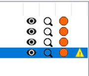
Vat leak sensor goes off
Continuous warning message on the GUI wit the print stopped – inspect resin vat leak sensors
If you notice a warning showing up on the GUI, then the blow peel sensors have been activated, suggesting a vat leak.
Vat leaks are caused when the vat film has been pierced or torn and resin has flowed under it into the sensor surface and blow-peel system. To prevent damage to the machine, the sensors activate valves to close, and the print is paused/cancelled. Remove platform and store in the dark. The user should then confirm if a vat leak has occurred and clean the leak immediately. If a false reading is given the build can be resumed however, discrepancies can occur in the print due to the pause with the likelihood of defects occurring increasing with the length of the pause. Watch the video to learn how to clean a machine after a vat leak.
-If you expect the need to re-calibrate the platform, please contact: support@photocentric.co.uk
That way the further troubleshooting with checks will be done before confirming this procedure.
Continuous loud tone – resin vat leak sensors
If you hear a loud tone and a vat leak warning has appeared on the GUI, then the blow peel sensors have been activated, suggesting a vat leak.
Vat leaks are caused when the vat film has been pierced or torn and resin has flowed under it into the blow-peel system. To prevent damage to the machine, the sensors activate, sounding an alarm and the print is paused/cancelled. Remove platform and store in the dark. The user should then confirm if a vat leak has occurred and clean the leak immediately if so. If a false reading is given the build can be resumed however, discrepancies can occur in the print due to the pause with the likelihood of defects occurring increasing with the length of the pause. Watch the video to learn how to clean a machine after a vat leak.
If you need to re-calibrate the platform please contact support@photocentric.co.uk
Blow peel
- Blow peel doesn`t operate
Check the main air supply for leakage/blockage and do the test again.
Remove the rear panel and inspect if the air valve is set correctly.
Photocentric Studio
- Lost License Key
If the license has been lost, we can reset it for a charge as follows
- Activating Studio license on a different system
To transfer your studio license to a different system, you need to first deactivate the license on your current system. Open the software and navigate to the ’Help' tab. Select the option to remove the license from the current system. This action will deactivate the license on that computer, this process requires an active internet connection.
Diagnosing print defects
Nothing attached to platform
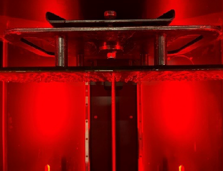
Appearance:
Nothing has printed on the platform and the part remains sitting in the vat submerged in resin.
Causes:
Software- part is positioned above the platform in the slicing software.
Platform- is too smooth or not homed correctly.
Reaction too slow- resin cold or exposure time too short.
Troubleshooting:
Software- To check your file is starting at the correct z-height on the platform, you can visually step through the first layers by moving the slice slider on the right side of your preview window with the shortcut PgUP and PgDN buttons on your keyboard.
Platform- If the platform has become too smooth it may no longer attach to the polymer. Take a fine (40 grit) sandpaper and rub it in a circular motion on the surface to deliver a key.
If it is not homed correctly, it may be starting the print above the LCD screen, rehome following these instructions here
Reaction too slow- Check you have heated the resin up before filling in the vat as some grades are less reactive at low temperatures than others. 35C is a good temp to start a print at.
Check the correct resin setting has been selected for the grade you are using.
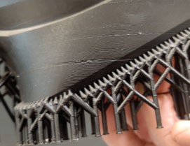
Base layers only
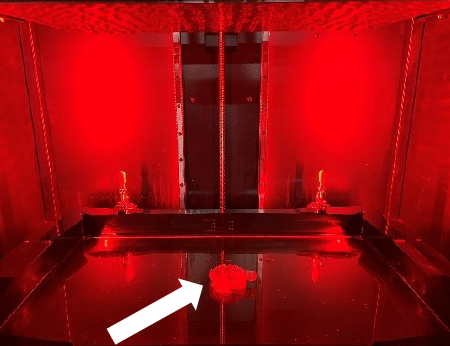
Appearance:
Only the first base layers have been formed attached to the platform, the rest of the print (arrow) is in the vat.
Causes:
Reaction too slow- resin too cold or exposure time too short.
Blow Peel is not working- Blow Peel gasket is damaged and leaking air.
Troubleshooting:
Reaction too slow- Check you have heated the resin up before filling in the vat as some grades are less reactive at low temperatures than others. 35C is a good temp to start a print at. Check the correct resin setting has been selected for the grade you are using.
Blow Peel is not working- Check by running a blow peel test, follow the video instructions here.
Supports only
Appearance:
Only supports are formed with the main part sitting in the vat.
Causes:
Wrong support profile selected.
Support tip diameter too small.
Under curing caused by wrong resin profile
Blow Peel failure.
Troubleshooting:
Wrong support profile selected- if it is too narrow or sparsely distributed it wont be strong enough to support the part, check our design guidelines here
Support tip diameter too small- if it is too small it wont be strong enough to support the part, each material has minimal feature size that it can hold. Check our design guidelines here
Under curing caused by wrong resin profile- each type of material has different exposure time. If you slice file with wrong profile the exposure time may not be long enough to form the supports and the model will fail.
Blow Peel failure– check by running a blow peel test, follow the video instructions here. If Blow peel stop working during the printing process, peel force may be big enough to pull model off the supports. On the GUI press ‘Maintain’ and then press ‘Pump’ to do test and see if it holds the air between the screen plate and vat film. If it deflates then remove the resin vat and check the blow peel gasket is sitting flat on the screen. Check if there are no holes in the vat. Check the air pipes for a loose connection.
Part breaks later in the build
Appearance:
The part is perfectly formed only to a level, the rest of the print is in the vat.
Causes:
Electricity stopped- power cut during the print
Slice missing in file- from mesh error
Part has structural design weakness- either supports or the object itself aren’t present
Vat leak - resin is under the vat
Blow Peel not working– Blow Peel gasket did not sit correctly
Debris in the vat– large solid particles in the resin
Troubleshooting:
Electricity stopped- check you didn’t have a power cut, the print would not restart.
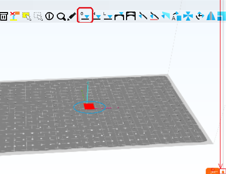
Slice missing in file- check your file is complete and there are no blank image files at around where the break happens by stepping through the layers around where it failed, by moving the slice slider on the right side of your preview window with the shortcut PgUP and PgDN buttons on your keyboard you will see if there is a file with a blank slice in it (ie no or a significantly reduced amount of white pixels). If there is remove it or correct it.
Check part list if there is a mesh error notification on front of any part. If there is any, use mesh repair tools to fix the part ![]()
Part has structural weakness in design- check the part doesn’t have a large change in the cross-sectional area at around the height it ceased to build, if it does re-position it at an angle and support it more densely.
Vat leak- check there isn’t any resin under the vat. If there is change the vat film https://iz0.b72.myftpupload.com/liquid-crystal-magna-resource-hub/
Blow Peel not working- check by running a blow peel test, follow the video instructions here. On the GUI press ‘Maintain’ and then press ‘Pump’ to do test and see if it holds the air between the screen plate and vat film. If it deflates then remove the resin vat and check the blow peel gasket is sitting flat on the screen. Check if there are no holes in the vat. Check the air pipes for a loose connection.
Debris in the vat- large solid particles in the vat can cause the next layer to not be able to start at the correct height. Filter resin back into the bottle, clean vat with IPA. Clean platform, take care to ensure there are no solid particles left in the holes or on the upper side of the platform.
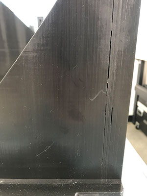
Crack
Appearance:
Cracks are a break in the part, either created during printing or after post exposure.
Causes:
Large amount of mass which shrinks by more than a smaller mass, then the only way it can neutralise the force is to pull apart.
High infill or internal support density.
Unsupported islands inside hollow parts.
Troubleshooting:
Large amount of mass which shrinks by more than a smaller mass- Avoid sudden surface area change during the print, orientate your part in 45-degree angle if possible. Support your file with external supports, then hollow and then add the infill. Do not hollow first or the software will automatically generate internal supports in the voids.
High infill or internal support density- There are many different lattice structures, both geometric and organic that can maintain strength and minimise mass. Then add necessary drain holes to ensure that complex internally latticed structures can be washed thoroughly. Rinse and leave to dry for 4 hours before putting it in the curing unit.
Unsupported islands inside hollow parts- Check for islands inside the hollow cavity by clicking ‘’Show Islands’’ highlighted or use Slide bar to check the part. Manually support islands if necessary.
![]()
Warping
Appearance:
The part has twisted away from its intended shape.
Causes:
It is caused by the cumulative effect of shrinkage being distributed unevenly through the print.
Troubleshooting:
Eliminating warpage in every possible geometry requires experience, but it can always be achieved if you use a combination of:
- Orientate your part on the platform so that any rapid changes in area from slice to slice and moderated, this can mean positioning it a different angle to the vertical.
- Avoid sadden surface area change during the print.
- Use a lattice to replace solid elements, VoxelDance Additive software will ensure a strong lattice support network, reducing mass and therefore shrinkage.
- Using a dense network of external supports to hold the part in place during printing.
- Dry the parts thoroughly before post processing.
- Keeping the part with its supports on, still on the platform until after post processing.
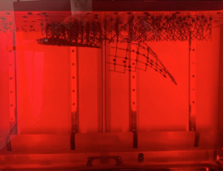
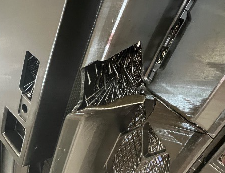
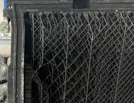
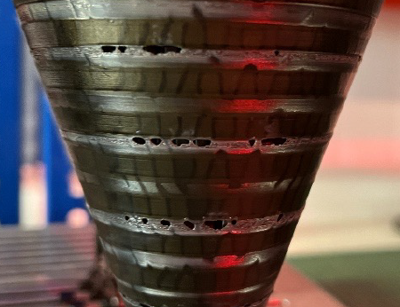
Vertical Line
Appearance:
Vertical line that travels all way up the part.
Causes:
Screen failure creating a stuck line or a stuck pixel.
Troubleshooting:
Screen failure creating a stuck line or a stuck pixel- these are caused by huge peeling forces when print large solid flat objects that lift the screen and damage the ribbon cable. It is caused by printing large solid objects (over 30% of the screen area) and orientating them horizontally. To avoid it in future, orientated part at 45-degree angle and hollow the part if solid area is larger than 30x30mm for Hard materials, or 80x80mm for Durable materials.
Horizontal Line
Appearance:
The part has a noticeable line in it that isn’t part of the design. It can extend to lead to a break at the outside of the part.
Causes:
Debris in vat causes the part to be positioned above the correct level at the next layer’s exposure.
Slice missing in print file.
Part design has significant structural weakness in its shape causing structural failure.
Vat film is too lose and doesn’t disengage from the part fully at peel.
Weak support structure that isn’t strong enough to withstand forces during build.
Troubleshooting:
Debris in vat- these can be observed by tracing the line back to the start of the error where you should find the chip of polymer sticking out. Filter resin back into the bottle, clean vat with IPA. Clean platform, take care to ensure there are no solid particles left in the holes or on the upper side of the platform.
Slice missing in file- check your file is complete and there are no blank image files at around where the break happens by stepping through the layers around where it failed, by moving the slice slider on the right side of your preview window with the shortcut PgUP and PgDN buttons on your keyboard you will see if there is a file with a blank slice in it (ie no or a significantly reduced amount of white pixels). If there is remove it or correct it.
Check part list if there is a Mesh error notification on front of any part. If there is any, use mesh repair tools to fix the part. ![]()
Part has large structural weakness in design- check the part doesn’t have a large change in the cross-sectional area at around the height of the line. Sudden changes in the surface area create uneven shrinkage, with the tension only being released by the part separating at that level. To reduce this, orientate the part at 45 degrees to the xy axis and avoid the presence of large overhangs. Failure to support the part adequately will mean that newly formed large areas will shift away and cause misalignment at that layer.
Vat film is too lose – make sure vat film has no visible creasing and isn’t too floppy. Change the vat film every 30 prints to maintain the correct film tension.
Weak support structure- ensure it is strong enough to withstand from any movement during the peeling and gravity force. If model has too few supports or the support diameter is smaller than recommended, the model can move or shift during the print, which will cause lines, layer shifting or delamination. Follow the Photocentric design guidelines for supporting parts here
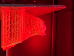
Cupping
Appearance:
Cupping, or a blowout, is a hole in the side wall of a spherical object.
Causes:
Cupping is caused when a hollow or convex portion of a part acts as a suction cup and traps air while printing. In printing a cup when the build platform pulls away from the screen during the peel process, the empty space within the cup increases its size and reduces the pressure within the cup to push the wall inward.
Troubleshooting:
Cupping tends to be more pronounced with resins that have low green strength or higher viscosity. It is evident in perfectly spherical shapes, large cup-like designs, or ones with very thin walls.
To minimize cupping:
- Orient the part to print at an 45-degree angle.
- Add a blow hole at the bottom of the design.
- Increase the wall thickness.
Consult the design guidelines recommended for your specific material and printer model here
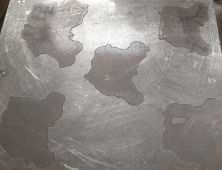
Sludging
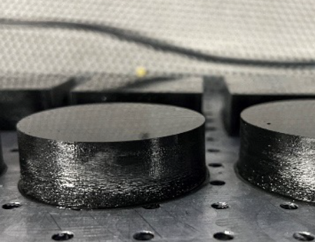
Appearance:
There is excess cured resin attached to the part and a puddle of soft cured resin the vat.
Causes:
Over-exposure of the resin with the resin moving while still curing. It is most visible in large solid objects above 30x30mm.
Troubleshooting:
It is caused by having resin that is too hot or the dwell cycle too short. If the part is larger than an area of 30x30mm it must be hollowed or orientated in angle. The larger the surface area the longer the delay time necessary, extend the ‘Delay time’ in ‘Print Settings’. Do not exceed a single solid area larger than 20,000 mm2 and do not use a solid boundary box size larger than 200x122mm. If the model is larger than these dimensions you must hollow or lattice the model.
Line formed on part 20-30mm from start
Appearance:
Causes:
This line is caused by the suction forces during printing when the part breaks above the level of resin in the vat, with no way of releasing the pressure. The hole in the base doesn’t release air pressure when it breaks the level of resin in the vat.
Troubleshooting:
Add a hole in the side wall to allow air to come in and out.
Post Processing
Information on how to use your Photocentric Wash XL and Photocentric Cure XL can be found in the user manuals below.
Technical & Application Guides
Dimensional Accuracy
Dimensional accuracy is a critical performance metric for any additive manufacturing platform. The Technical Note below outlines the factors that influence the accuracy, precision, and repeatability of parts printed on the LC Titan. It also details how LC Titan hardware, materials, and workflow contribute to consistent performance across the build volume.
The purpose is to equip our technical users with practical insights to achieve optimal results with LC Titan in demanding manufacturing environments.
Guidelines for Printing Props
Everything you need to know to make amazing props using LC Titan and Photocentric resins.
Guidelines for Casting
The following design rules will help achieve a successful and dimensionally accurate print and cast results, as part of preparing your CAD file ready for print
Guidelines for Shoe Moulds
Printing shoe moulds with HighTemp DL401 resin & VoxelDance Additive software on Liquid Crystal Titan
Photocentric Studio
Preparation of models in Photocentric Studio is one of the most important steps of the printing process and it is worth spending time to really understand how to support and orientate parts on your Magna printer. Note, this process may differ from other printers you have used.
Applying optimised supports and part orientation is critical to making parts within tolerance, obtaining excellent surface finish and achieving fast production times.
When orienting your parts think about:
- centre of gravity- this will change as your geometry changes through the print.
- suction - avoid a cupping effect by incorporating vent holes
- Peel forces- counter any pull downwards by angling the part to minimise the surface area per layer, aiming for a gradual increase in surface area.
- Supports are needed only when there is an overhang or a flat surface facing the platform.
- Surface finish- support the part in areas surface finish is not important and to minimse time spent removing supports.
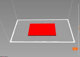
General Rules for Orientation and Supports:
To achieve dimensional accuracy and to compensate for any shrinkage, we recommend scaling up the model in volume by 0.5% in all three axes (xyz).
Do this before slicing or set it as your default by opening your chosen resin profile, select the ‘Part pre processing’ tab and click on ‘Shrinkage correction scale XYZ’ to change values to 1.005 in all three axes (ie. Increasing the volume by 0.5%). Press ‘save’, then, every time you select this resin the scaling factor will be automatically applied.

Figure 1: Shrinkage Correction Scale
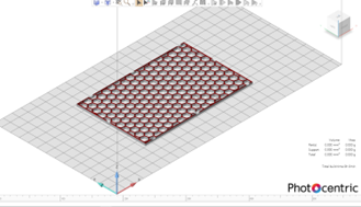
Positioning Models
Placing models too close to each other (such as when printing multiple copies of the same model) will adversely affect the surface quality of your parts and make washing the parts more difficult. It can also make achieving complete post processing on the platform harder as light will not be able to reach all areas evenly.
- Keep at least 3mm between parts. For black resins, the minimum distance between models should be 5mm.


Supporting Prints
When using supports, raise parts to a minimum height of 10 mm above the platform to allow:
- More complex support structures
- Easier part removal from the platform
- Easier support removal from the part
- When printing large surfaces, increase the height of supports to 20-30mm.
Minimum wall thickness
- for rigid resins such as High Tensile and Hard set it to 0.5mm
- for flexible resins such as Flexible set it to 2mm
Minimum support tip diameter
- for all rigid materials is 0.6mm
- for all flexible resins is 1.2mm
Tips & tricks for orientating models
Flat parts are better printed vertically

Flat models with large surface areas should not be printed flat, directly on the build platform or with short supports. Large surface areas attach too well to the platform and are easily damaged when removing them. In addition, resin flow will create a rough surface around the model. Printing flat and/or on short supports may cause the model to deform through shrinkage and takes longer to remove support material.

Flat models should be printed vertically. The model can then be placed directly on the build platform. Alternatively, lift the model 10mm above the build platform and support the bottom surface.
This orientation minimises the surface area requiring supports. The model will then look smooth from both sides and less time spent on removing supports.
Print at 45 degrees to the x, y and z axes

This model will have a rough surface on one face as the pixels shift across it. As it has only been orientated to the x axis.

To achieve a smooth surface finish and to avoid pixel shifting lines on flat surfaces, rotate your model to be 45 degrees to the x, y and z axes.
Angle boxes at 45 degrees to all axes and support 15mm off the platform

Just orienting large flat models in one or two axes will lead to deformation in the first few layers created by peeling forces and the change in centre of gravity.

Rotate flat or box-like large models at 45 degrees to all three axes and lift the model 15 mm from the platform.
This orientation results in a gradual increase in surface area, reducing the risk of warpage and anisotropic shrinkage in the printed model.
Printing vertically reduces the amount of supports necessary

Printing this part horizontally would need a lot of supports on the bottom surface, meaning longer file preparation and support removal in the post processing stage. The part could also deform without internal supports.

Orientating this type of model vertically will require fewer supports. The print will take longer than in a horizontal orientation, but you will save in less post processing and it will have a better surface finish.

Don’t print tubular shapes horizontally. The model will deform with the internal cavity changing from circular to oval. Adding internal supports can help to avoid deformation, however file preparation and post-processing time will increase.
Orienting this model at a 45 degree angle would require a lot of supports and extra post processing.

Support a tube vertically for best surface finish and dimensional accuracy. Lift the model by at least 10mm from the platform to avoid failure due to suction forces. Parts will also be easier to remove from the platform.
Introduction to Supports for Structure Elements
1) Support Tip
2) First Beam
3) Multiplier Top Joint
4) Pole
5) Foot

Recommended support settings for hard materials such as High Tensile, Hard or Durable
Default and recommended settings for first beam length and joint diameter.
In ‘Support mode’, click on ‘ Support Generation (Advanced)’ tab.
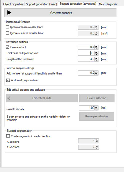
Click to enlarge
Support settings for small models (up to 100mm build height).
In ‘Support mode’, click on ‘Support Generation (basic)’ tab.

Click to enlarge
Minimum supports for medium models (up to 200mm build height).
In ‘Support mode’, click on ‘Support Generation (basic)’ tab.

Click to enlarge
Minimum supports for large models (up to 250mm build height).
In ‘Support mode’, click on ‘Support Generation (basic)’ tab.
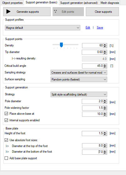
Click to enlarge
Minimum supports for very large models
(up to max build height)
In ‘Support mode’, click on ‘Support Generation (basic)’ tab.

Click to enlarge
Minimum Internal support dimensions.
Click on ‘Configuration’ from ‘File’ menu.
Double click on ‘Liquid Crystal Magna’, then ‘Manual Support’ tab.

Click to enlarge
Minimum internal support dimensions where the distance between two walls is over 50mm.
Click on ‘Configuration’ from ‘File’ menu.
Double click on ‘Liquid Crystal Magna’, then ‘Manual Support’ tab.

Click to enlarge
Minimum tree support dimensions.
Click on ‘Configuration’ from ‘File’ menu.
Double click on ‘Liquid Crystal Magna’, then ‘Manual Support’ tab.

Click to enlarge
Minimum single support dimensions for models up to 100mm tall
Click on ‘Configuration’ from ‘File’ menu.
Double click on ‘Liquid Crystal Magna’, then ‘Manual Support’ tab

Click to enlarge
Minimum single support dimensions for models up to 150mm
Click on ‘Configuration’ from ‘File’ menu.
Double click on ‘Liquid Crystal Magna’, then ‘Manual Support’ tab

Click to enlarge
Minimum single support dimensions for models up to 250mm
Click on ‘Configuration’ from ‘File’ menu.
Double click on ‘Liquid Crystal Magna’, then ‘Manual Support’ tab.

Click to enlarge
Minimum single support dimensions for models for maximum build height
Click on ‘Configuration’ from ‘File’ menu.
Double click on ‘Liquid Crystal Magna’, then ‘Manual Support’ tab.

Click to enlarge
Recommended support settings for soft materials like Flexible
Default and recommended settings for first beam length and joint diameter.
In ‘Support mode’, click on ‘ Support Generation (Advanced)’ tab.
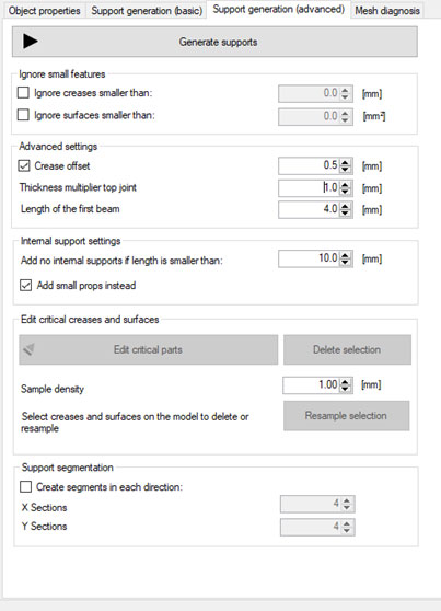
Click to enlarge
Minimum supports for small models (up to 100mm build height).
In ‘Support mode’, click on ‘Support Generation (basic)’ tab.

Click to enlarge
Minimum supports for medium models (up to 250mm build height).
In ‘Support mode’, click on ‘Support Generation (basic)’ tab.

Click to enlarge
Minimum supports for large models (maximum build height)
In ‘Support mode’, click on ‘Support Generation (basic)’ tab.

Click to enlarge
Minimum internal support dimensions.
Click on ‘Configuration’ from ‘File’ menu.
Double click on ‘Liquid Crystal Magna’, then ‘Manual Support’ tab.

Click to enlarge
Tips & Tricks for Creating Support Structures
Click ’Support mode’ and choose.
![]()
This will automatically generate supports.
Always visually check all the critical areas have been supported.

If there are areas which require extra supports press
![]()
When you see the non-supported areas click on the areas that need reinforcing to add additional supports.
The distance between supports should be 2-3mm. An indicative measure is that the platform grid size is 5x5mm.
Once all of the critical areas are supported, press ![]()


Automatic supports do not always add supports to all critical areas. In this photo, supports on the bottom have only been added to one edge. This model will fail or deform in this area due to gravity and peeling forces.

When using automatic supports, always edit to add more supports as necessary. Supports need to be strong enough to hold the model and resist the pull of gravity and peel forces during printing. Supports must also be as close as possible to the edge of the model.

In some cases, automatic supports are not sufficient. In the above example, manual supports should be added to support the critical angles and make the structure strong enough to hold the part. If printed without extra supports, the part will fail or deform during printing.

This is an example of an optimised combination of automatic supports and manual adjustments. All critical angles are supported, the supports are evenly distributed and with the correct density.


Without supports on both edges, the first layers will start to deform, the edges will not be cleanly defined and print failure may result.

First layers are very important. Angled edges must be supported from both sides to keep a defined, sharp edge.

Positioning the part vertically over the plate, directly or on supports will cause the first few layers to deform and lead to warping.

If the model size and shape allows, orient it at an angle to all axes.


A distance between support tips of more than 3mm will lead to a rough surface where there are overhangs. Distances of more than 5mm will create deformation and delamination.

The distance between supports should be less than 2mm and as close to the edge as possible.

Support tips should be close to the edge.

If support tips are too far from the edge, the model will be rough and deformed.

Without internal supports, holes will deform and become oval in shape.

For round holes larger than 2mm in diameter add one internal support.

Support feet angled downwards as above will be harder to remove.

Adding support feet angled upwards as shown, will make part removal easier.


Don’t print large models flat. It will be very hard to remove them from the platform and they may break.
Printing this part as shown, with overhanging horizontal surfaces will require internal supports to avoid deformation. These would be extra post processing and give a poor surface finish.

Orientate this type of model vertically with no supports. Print time will be longer than orientating horizontally, but the part will need less post processing time and will subsequently have a better surface finish. Orientate parts with internal overhangs so they require minimum internal supports. The best option is to align this part with overhangs vertically to the build plate, giving the best surface finish on both sides.

If features overhang by more than 1mm and have sharp angles add supports to keep the edge sharp.

If features overhang by more than 2mm and have rounded angles add supports to keep the edge shape.

If overhangs are shorter than 2mm and are self-supporting on both sides, there is no need to add supports in the middle.
Hollowing
Photocentric Studio has an option to hollow large models (model geometry and application permitting).
Hollowing will reduce resin usage, hence print cost. It also reduces weight which can help improve the print quality and success rate.
Minimum wall thickness for ‘Investment Casting’ application is 0.5mm and for general large prototyping models is 2mm.

Once hollowing is complete, we recommend adding an infill structure to make models more rigid and to support internal overhangs.
Minimum infill diameter is 0.5mm for ‘Investment Casting’ parts, with cell size of 5mm.
Default settings are 1mm infill diameter and 5 mm cell size.

In 'Transparent View', you can check the infill structure.
Hollowing and infill can save up to 80% of resin while still keeping models rigid.
Hollow models need drain holes to reduce the suction effect during printing.
Choose ‘Flexible drainage hole’ ![]() in ‘Support’ mode.
in ‘Support’ mode.
Minimum drain hole diameter is 4 mm.


Without drain holes in hollow models eg, bottles, the force inside the model can break the wall or create visible lines across the whole model.

Hollow models need drain holes to be added. Drain holes reduce the suction cup effect during printing.
Example 1

If you orient this model with a sharp angle as shown here, it will lead to an unneccessarily long print time, more supports will need to be used giving an increased post processing time and you will have a poor surface finish.

The best orientation for a box-like model, is to lift the part from the plate by 10mm, rotate it around all three axes and support the bottom surface sufficiently.

Example 2

Automatically generated supports for a tablet case lid.

Edge sides are not properly supported and will be deformed during the print. The first few layers will warp and deform due to peeling forces and the lack of supports.

The automatic support function only recognises outer edges as overhangs and does not support internal surfaces which are still cititical areas.

Printing this model vertically with length or width parallel to the plate, will result in deformation in the first few layers. The top edge overhang may also deform. Where possible, follow the gradual build up rule, building from a smaller surface to a larger surface area gradually.

After applying automatic supports, manual supports on the internal surfaces are needed. Additional supports should be added, evenly spaced and covering all internal areas.

Optimised support structure after manual adjustments.

If you have enough space, we recommend printing this part vertically at an angle of 45 degrees to the platform.
Print time will be longer, but post processing time shorter, as internal surfaces are self-supported. Surface finish will also be better.
Make sure the part is lifted by 10mm from the plate.

Example 3

This is not a recommended orientation. Now all of the fins are overhangs and need supporting (automatic supports would not be enough). This orientation would create more work to support and to finish.

Think about how to minimise overhangs when considering print orientation. Here, the engine fins are kept intact with minimum post processing time, only needing supports on one side. You can also add some internal supports inside the cylinder.

To avoid deformation, print thin, flat surface areas vertically. If you orient this model at 45 degrees, the main body will print well, but the fins will deform slightly as they have not been supported enough to overcome peeling forces and gravity.

This is an optimised combination of using automatic supports at 5% density with manual support adjustments.

If positioned at a 45 degrees angle it is not possible to support fins sufficiently and after printing 2-3mm the fins will start to deform.

An overview of where manual support tips should be added.